


4
The buzzer installation requires two cable ties and two wire nuts or
other wire connectors.
If you need to extend any of the buzzer or dash light wires, use a
minimum of 24 gauge wire and wire connectors of your choice. Wire
nuts or electrical tape are required to cap any unused bare wires.
Installation Sequence
You can install this gauge in some other order if you prefer, but we
recommend the installation sequence summarized below:
1. Determine the location for the gauge so you can plan how and where
to route the cables. This will help you make sure you have enough cable
length for the desired configuration.
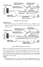
2. Determine the location of the nearest device on the boat's NMEA
2000 network, along with the route of the gauge's network cable.
3. Determine the location for the alarm buzzer (piezo) and its wire
route.
4. If you want to turn on the gauge's backlight whenever you turn on
your dashboard lights, locate your boat's dash light switch and
determine how to route the gauge's dash light wires to it.
5. Install the gauge in a standard 2-1/8" (54 mm) hole in the dash. If no
2-1/8" (54 mm) hole in the dash, use a hole saw to cut a mounting hole.
6. Connect the buzzer wires and install the buzzer. If desired, connect
the dash light wires to the boat's dash light switch.
7. Connect the network cable to the NMEA 2000 network.
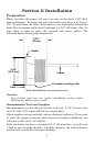
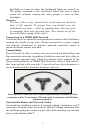
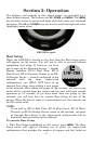
Mounting the Gauge
When you determine the location for the LMF-200, drill a 2-1/8" (54
mm) hole in the dash or use an existing gauge hole. Slide the unit's
cables through the hole from the front side of the dash. Push the LMF-
200 housing through the hole until it is flush with the dash surface.
Make sure the face of the gauge is aligned correctly.
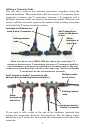
Next, slide the rubber gasket and plastic-mounting collar over the
cables and onto the back side of the gauge.