


1. FUNCTIONS AND CONFIGURATION
1 - 6
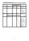
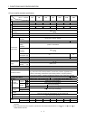
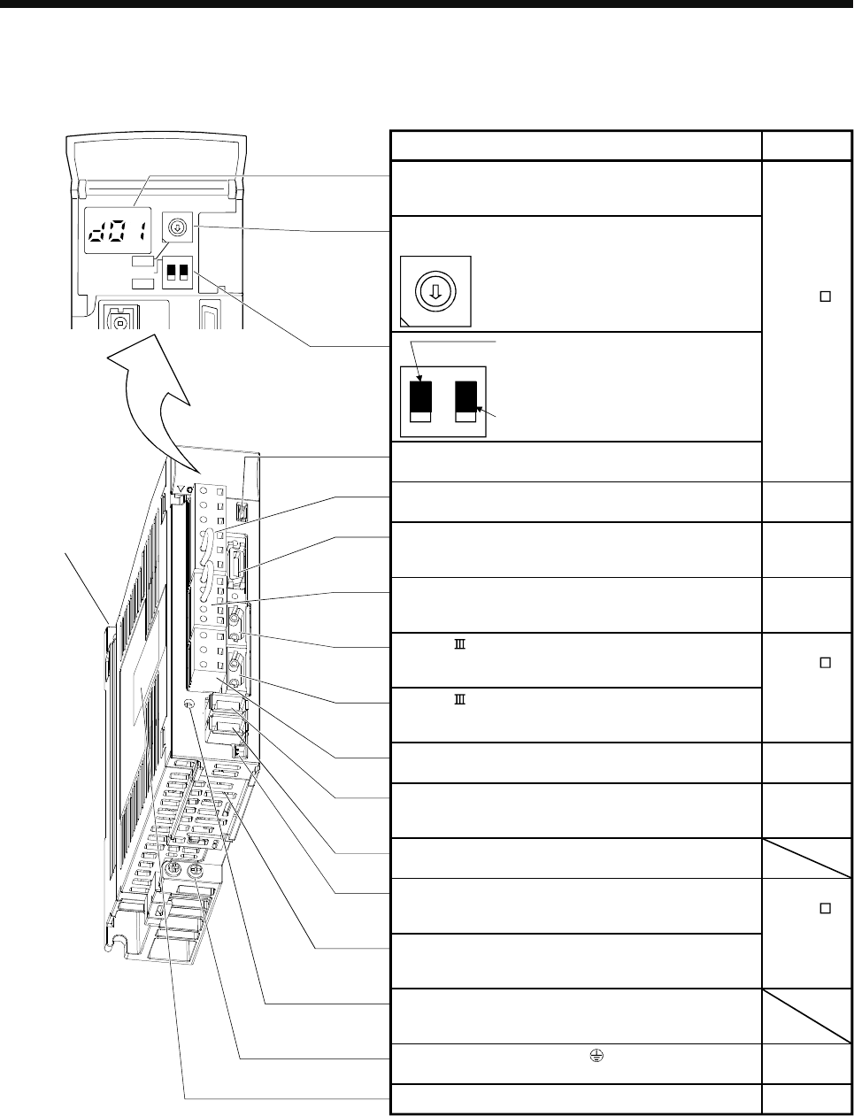
1.6 Parts identification
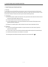
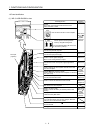
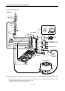
(1) MR-J3-100B-RJ080W or less
Charge lamp
Lit to indicate that the main circuit is charged. While this
lamp is lit, do not reconnect the cables.
5
3
4
7
9
6
8
2
1
0
F
E
D
C
B
A
ON 4E
12
SW1
SW2
TEST
Fixed part
(2 places)
SW2
8
7
6
5
4
3
2
1
0
F
E
D
C
B
A
9
2
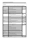
Display
The 3-digit, seven-segment LED shows the servo
status and alarm number.
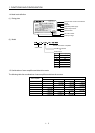
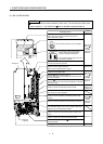
Rotary axis setting switch (SW1)
Used to set the axis No. of servo amplifier.
SW1
Test operation select switch (SW2-1)
Used to perform the test operation
mode by using MR Configurator.
For manufacturer setting (Be sure to set
to the "Down" position).
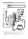
Main circuit power supply connector (CNP1)
Connect the input power supply.
USB communication connector (CN5)
Connect the personal computer.
I/O signal connector (CN3)
Used to connect digital I/O signals.
More over an analog monitor is output.
Control circuit connector (CNP2)
Connect the control circuit power supply/regenerative
option.
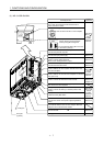
SSCNET cable connector (CN1A)
Used to connect the servo system controller or the front
axis servo amplifier.
SSCNET cable connector (CN1B)
Used to connect the rear axis servo amplifier. For the final
axis, puts a cap.
Direct drive motor power output connector (CNP3)
Connect the direct drive motor.
Encoder connector (CN2)
Used to connect the direct drive motor encoder.
Connector for manufacturer setting (CN2L)
Not used for this servo amplifier.
Battery holder
Install the battery MR-J3BAT.
Protective earth (PE) terminal ( )
Ground terminal.
Rating plate
1
Refer to the
MR-J3- B
Servo
Amplifier
Instruction
Manual.
Section 3.2
Section 3.3
Section 3.2
Refer to the
MR-J3- B
Servo
Amplifier
Instruction
Manual.
Chapter 2
Section 3.2
Section 3.2
Section 1.4
Name/Application
Detailed
explanation
Chapter 2
Section 3.4
Chapter 9
Battery connector (CN4)
Used to connect the battery for absolute position data
backup.
Refer to the
MR-J3- B
Servo
Amplifier
Instruction
Manual.