


3. SIGNALS AND WIRING
3 - 10
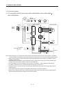
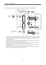
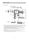
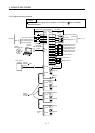
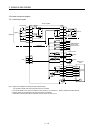
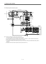
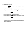
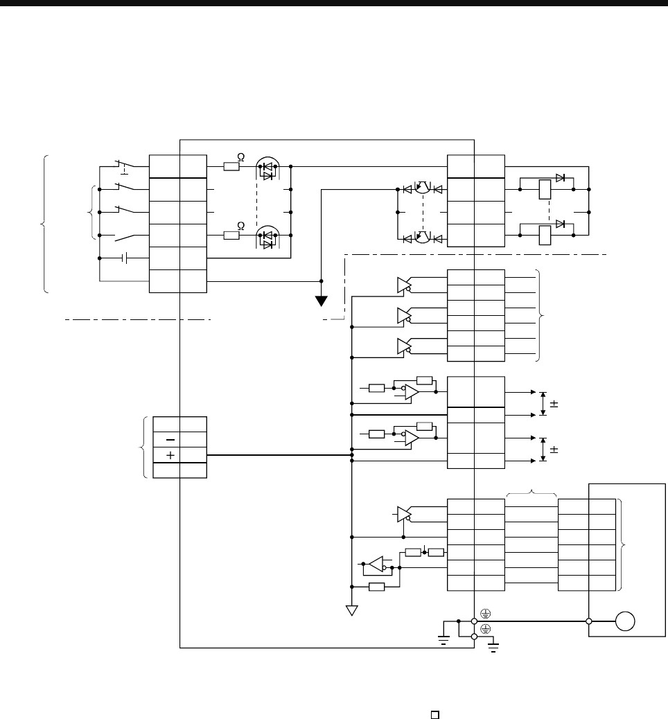
3.5 Internal connection diagram
3.5.1 Incremental system
3
EM1
CN3
20
DI1 2
DI2 12
DI3 19
DICOM
5
3
CN3
10
13
9
15
DICOM
INP
ALM
CN3
6
16
7
17
8
18
LA
LAR
LB
LBR
LZ
LZR
CN3
MO1
MO2
LG
4
14
11
Differential line
driver output
(35mA or less)
<Isolated>
Approx.
5.6k
Analog monitor
Servo amplifier
2
4
MR
MRR
LG
E
(Note 1)
USB
M
D
GND
VBUS
D
1
2
3
5
CN5
LG1
MBR
DOCOM
24VDC
Forced stop
CN2
RA
RA
5THM1
6THM2
P5
(Note 4)
Direct drive
motor
7
10
8
MR
MRR
LG
6THM1
11THM2
1P5 9P5
(Note 3)
Encoder
(Note 2)
Approx.
5.6k
(Note 2)
10VDC
10VDC
Note 1. Signal can be assigned for these pins with controller setting.
For contents of signals, refer to the instruction manual of controller.
2. For sink I/O interface. For source I/O interface, refer to section 3.7.3 of the MR-J3-
B Servo Amplifier Instruction Manual.
3. Speed, position and temperature of the direct drive motor are detected.
4. Fabrication of the encoder cable is required at user side. (Refer to section 9.1.2.)