


2. DIRECT DRIVE MOTOR
2 - 12
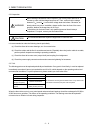
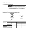
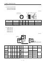
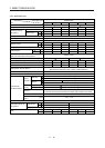
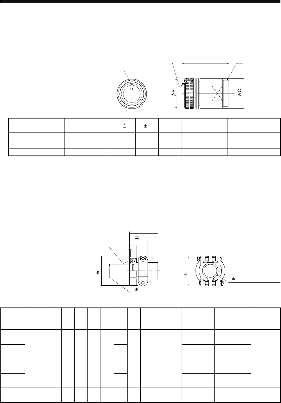
(b) CE05-6A18-10SD-D-BSS
CE05-6A22-22SD-D-BSS
CE05-6A32-17SD-D-BSS
[Unit: mm]
A
D
W
Positioning key
Model A B
0
0.38
C 0.8 D or less W
Connector configuration
(Note)
CE05-6A18-10SD-D-BSS 1 1/8-18UNEF-2B 34.13 32.1 57 1-20UNEF-2A C
CE05-6A22-22SD-D-BSS 1 3/8-18UNEF-2B 40.48 38.3 61 1 3/16-18UNEF-2A D
CE05-6A32-17SD-D-BSS 2-18UNS-2B 56.33 54.2 79 1 3/4-18UNS-2A E
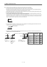
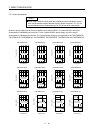
Note. For the connector configuration, refer to section 2.4.2.
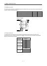
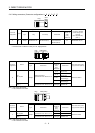
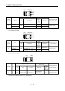
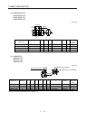
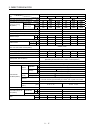
(c) CE3057-10A-1-D
CE3057-10A-2-D
CE3057-12A-1-D
CE3057-12A-2-D
CE3057-20A-1-D
[Unit: mm]
(D)
B
C
1.5
A 0.7
G 0.7
(Bushing outer diameter)
(Bushing inner diameter)
E
F
V-Thread
Model
Applicable
shell size
A B C (D) E F G V
Enclosed
bushing type
Range of
applicable cables
(Reference)
Connector
configuration
(Note)
CE3057-
10A-1-D
14.1 CE3420-10-1 10.5 to 14.1
CE3057-
10A-2-D
18 23.8 30.1 10.3 (41.3) 15.9
11.0
31.7 1-20UNEF-2B
CE3420-10-2 8.5 to 11
C
CE3057-
12A-1-D
16.0 CE3420-12-1 12.5 to 16
CE3057-
12A-2-D
22 23.8 35 10.3 (41.3) 19
13.0
37.3
1 3/16-18UNEF-
2B
CE3420-12-2 9.5 to 13
D
CE3057-
20A-1-D
32 27.8 51.6 11.9 (43.0) 32.0 23.8 51.6 1 3/4-18UNS-2B CE3420-20-1 22.0 to 23.8 E
Note. For the connector configuration, refer to section 2.4.2.