


4. OPERATION AND FUNCTIONS
4 - 13
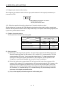
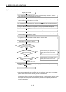
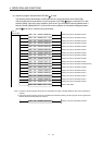
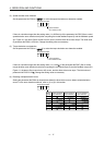
(a) Sequence program example when QD74MH
is used
The following shows the example of writing the axis No.1 servo parameter to the flash ROM.
After changing the servo parameter, turn on the power of QD74MH
again or reset the CPU, then
send the setting value to the servo amplifier. Refer to the Type QD74MH Positioning Module User’s
Manual (Details) (IB(NA)0300147) for the buffer memory address of the special setting parameters
(No.PS
) of the 2nd to 16th axis servo parameters.
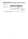
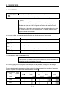
TOP H0 K10498 K100 K1
TOP H0 K10499 K100 K1
TOP H0 K10500 H0010 K1
TOP H0 K10504 H01F4 K1
TOP H0 K10509 H0000 K1
TOP H0 K10510 K0 K1
TOP H0 K500 K1 K1
(Note 1)
Write condition
Setting of the servo parameter No.PS06
Setting of the servo parameter No.PS07
Setting of the servo parameter No.PS08 (Note 2)
Setting of the servo parameter No.PS12
Setting of the servo parameter No.PS17
Setting of the servo parameter No.PS18
Write to flash ROM
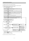
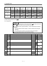
TOP H0 K10145 H0020 K1
TOP H0 K10493 H0001 K1
TOP H0 K10496 H0003 K1
TOP H0 K10497 K9 K1
Setting of the servo parameter No.PD03
Setting of the servo parameter No.PS01
Setting of the servo parameter No.PS04
Setting of the servo parameter No.PS05
TOP H0 K10301 H0060 K1
TOP H0 K10381 K3 K1
TOP H0 K10383 H0000 K1
Setting of the servo parameter No.PA01
Setting of the servo parameter No.PC01
Setting of the servo parameter No.PC03
TOP H0 K10146 H0021 K1 Setting of the servo parameter No.PD04
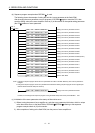
TOP H0 K10501 K30 K1
TOP H0 K10502 H0005 K1
TOP H0 K10503 H0064 K1
Setting of the servo parameter No.PS09
Setting of the servo parameter No.PS10
Setting of the servo parameter No.PS11
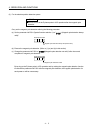
Note 1. Configure a sequence program where the servo parameters are written to the flash ROM only when a servo parameter is
changed.
2. Change the sequence program of the servo parameter No.PS08 to the following sequence program for the magnetic pole
detection without the stroke limit (FLS and RLS).
TOP H0 K10500 H0110 K1
Setting of the servo parameter No.PS08