


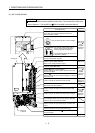

2. DIRECT DRIVE MOTOR
2 - 4
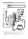
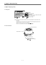
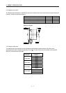
2.3.2 Installation orientation
The following table indicates the installation orientation of the direct drive motor.
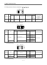
Direct drive motor series Direction of installation
TM-RFM May be installed in any direction.
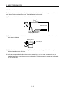
2.3.3 Load remove precautions
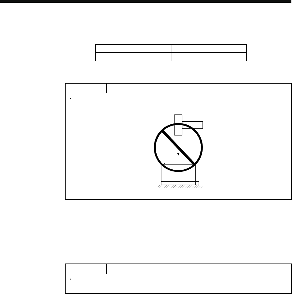
POINT
During assembling, the rotor end must not be hammered. Doing so can cause the
encoder to fail.
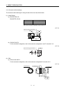
(1) The orientation of the encoder on the direct drive motor cannot be changed.
(2) For installation of the direct drive motor, use spring washers, etc. and fully tighten the bolts so that they do
not become loose due to vibration.
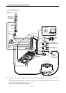
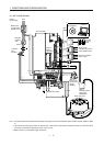
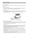
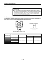
2.3.4 Permissible load for the rotor
POINT
Because the rigid coupling may damage the rotor, make sure to align and center
the load on the rotor.
For the permissible rotor load specific to the direct drive motor, refer to section 2.5.2.
(1) When coupling a load to the direct drive motor, the load applied to the rotor must be under the permissible
load.
(2) Excess of the permissible load can cause the bearing life to reduce and the rotor to break.
(3) The load indicated in this section is static load in a single direction and does not include eccentric load.
Make eccentric load as small as possible. Not doing so can cause the direct drive motor to be damaged.