


3. SIGNALS AND WIRING
3 - 2
3.1 Precautions for this chapter
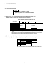
The following items are not described in this chapter. Since these descriptions are the same as those of MR-
J3-
B Servo Amplifier, refer to the MR-J3- B Servo Amplifier Instruction Manual.
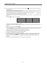
Item MR-J3- B Servo Amplifier Instruction Manual
Explanation of power supply system Section 3.3
Signal (device) explanations Section 3.5
Alarm occurrence timing chart Section 3.6
Interfaces Section 3.7 (excluding the internal connection diagram)
Treatment of cable shield external conductor Section 3.8
SSCNET cable connection Section 3.9
Grounding Section 3.12
Control axis selection Section 3.13
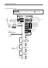
3.2 Input power supply circuit
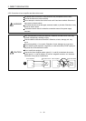
CAUTION
Always connect a magnetic contactor between the power supply and the main
circuit power supply (L
1
, L
2
, and L
3
) of the servo amplifier, and configure the wiring
to be able to shut down the power supply on the side of the servo amplifier’s power
supply. If a magnetic contactor is not connected, continuous flow of a large current
may cause a fire when the servo amplifier malfunctions.
Use malfunction (ALM) to switch main circuit power supply off. Otherwise, a
regenerative transistor fault or the like may overheat the regenerative resistor,
causing a fire.
Check the model and input the correct voltage for the power supply of the servo
amplifier. When a voltage, which exceeds the maximum input voltage of the servo
amplifier specifications, is input, the servo amplifier malfunctions.
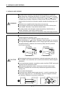
POINT
Even if alarm has occurred, do not switch off the control circuit power supply.
When the control circuit power supply has been switched off, optical module does
not operate, and optical transmission of SSCNET
communication is interrupted.
Therefore, the servo amplifier on the rear axis displays "AA" at the indicator and
turns into base circuit shut-off. The direct drive motor stops with starting dynamic
brake.
For details of each signal, refer to section 3.3 of the MR-J3- B Servo Amplifier
Instruction Manual.
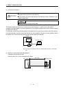
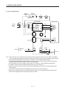
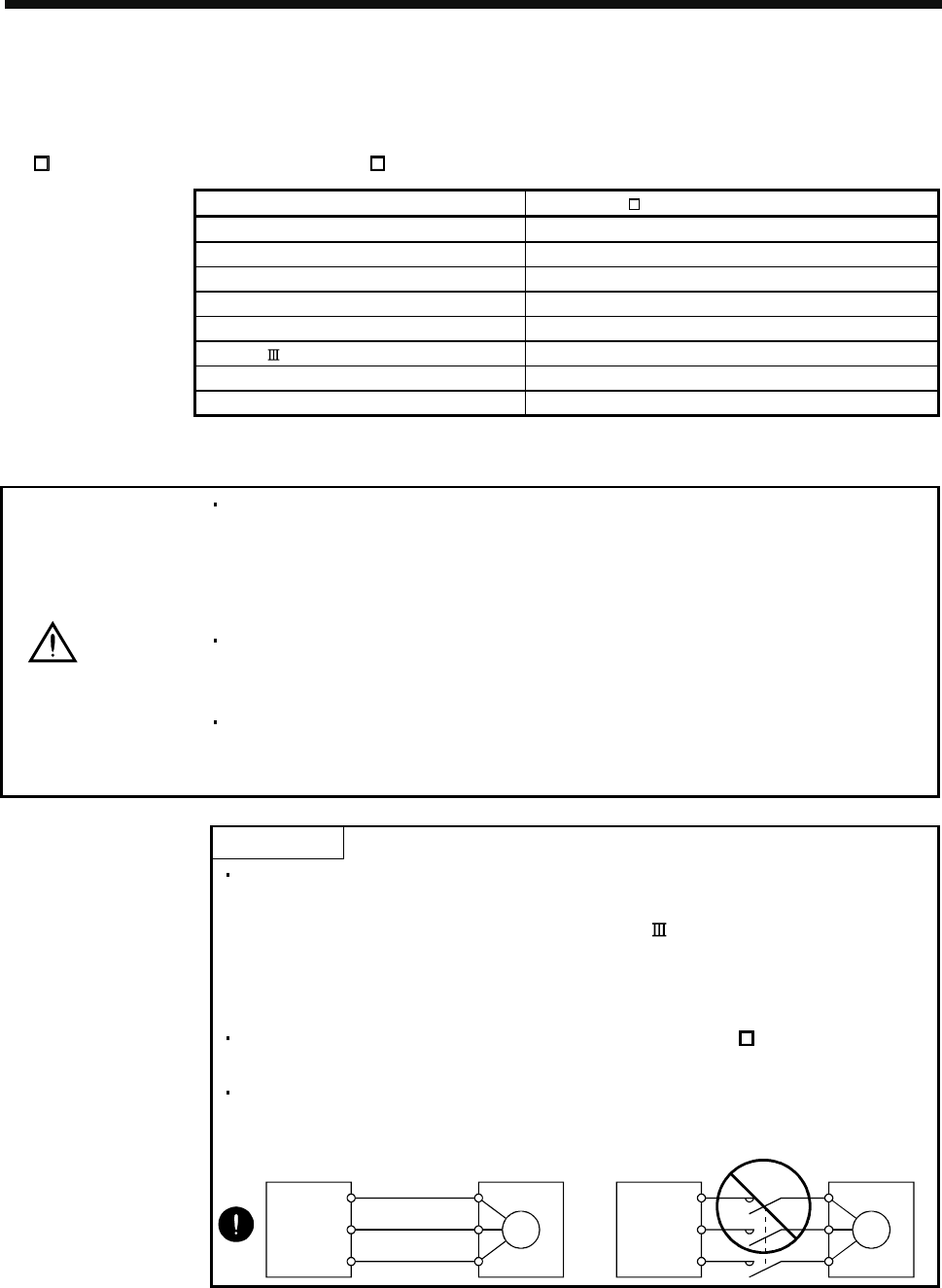
Connect the direct drive motor power terminal (U, V, and W) to the direct drive
motor power input terminal (U, V, and W) directly. Do not let a magnetic contactor,
etc. intervene. Otherwise, it may cause a malfunction.
U
Direct drive motor
M
V
W
U
V
W
Servo amplifier
U
M
V
W
U
V
W
Servo amplifier Direct drive motor
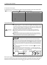
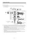
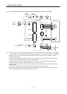
Wire the power supply/main circuit as shown below so that power is shut off and the servo-on command turned
off as soon as an alarm occurs, a servo forced stop is made valid, or a controller forced stop is made valid. A
molded-case circuit breaker (MCCB) must be used with the input cables of the main circuit power supply.