


3. SIGNALS AND WIRING
3 - 7
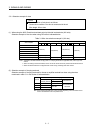
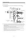
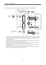
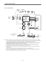
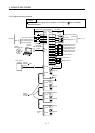
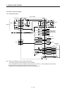
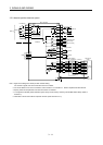
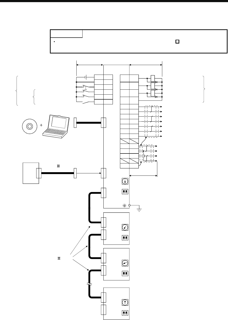
3.3 I/O signal connection example
POINT
For details of each signal, refer to chapter 3 of the MR-J3- B Servo Amplifier
Instruction Manual.
(Note 2)
(2 axis)
(3 axis)
(n axis)
(Note 6)
SSCNET cable
(option)
Personal
computer
(Note 3, 4) Forced stop
(Note 13, 14)
5
20
Encoder A-phase pulse
(differential line driver)
Encoder B-phase pulse
(differential line driver)
CN3
Encoder Z-phase pulse
(differential line driver)
4
(Note 12)
Magnetic brake interlock
(Note 16)
Plate
MO1
1LG
14 MO2
SD
13 MBR
9INP
15 ALM
10
DICOM
6LA
16 LAR
7LB
17 LBR
8LZ
18 LZR
Servo amplifier
CN1A
Servo system
controller
CN5
(Note 5)
MR Configurator
3
Malfunction
(Note 11)
In-position
CN3
(Note 12)
(Note 6)
SSCNET cable
(option)
CN1A
CN1B
(Note 7)
(Note 9)
Cap
(Note 1)
CN1B
SW1
21
SW2
SW1
21
SW2
11 LG
Control common
(Note 8)
(Note 8)
CN1A
CN1B
(Note 7)
SW1
21
SW2
(Note 8)
CN1A
CN1B
(Note 7)
SW1
21
SW2
(Note 8)
(Note 10)
24VDC
(Note 14)
(Note 15)
DICOM
EM1
DOCOM
2
19
12
DI1
DI3
DI2
Upper stroke limit (FLS)
Lower stroke limit (RLS)
Proximity dog (DOG)
2m or less
Analog monitor 1
Analog monitor 2
MR-J3-B-RJ080W
MR-J3-B-RJ080W
MR-J3-B-RJ080W
USB cable
MR-J3USBCBL3M
(option)
RA1
RA2
RA3
10m or less 10m or less