


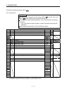
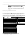
5. PARAMETERS
5 - 10
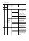
Classification No. Symbol Name and function
Initial
value
Unit Setting range
PS06 LB2 Servo control speed deviation error detection level
Used to set the speed deviation error detection level of the servo control
error detection. When the difference between the model feedback
speed and the feedback speed is bigger than this setting value, the
servo control error is detected (42). (Refer to section 4.4)
100 r/min 1 to 2000
PS07 LB3 Servo control to torque deviation error detection level
Used to set the torque deviation error detection level of the servo control
error detection. When the difference between the command torque and
the feedback torque is bigger than this setting value, the servo control
error is detected (42). (Refer to section 4.4)
100
1 to 1000
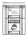
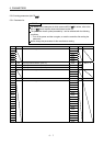
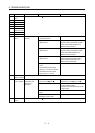
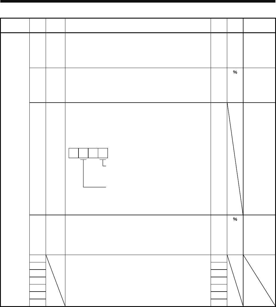
PS08 *LIT3 Special function selection 3
Select the valid/invalid setting of the stroke limit and the magnetic pole
detection method for the magnetic pole detection. (Refer to section
4.2.3)
When the stroke limit (FLS and RLS) of the servo amplifier is not used,
invalidate the stroke limit for the magnetic pole detection.
Method selection for the magnetic pole detection
0: Position detection method
4: Minute position detection method
10
Valid/invalid setting of the stroke limit (FLS and
RLS) for the magnetic pole detection
0: Valid
1: Invalid
0010h Refer to the
name and
function
column
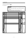
PS09 LPWM
Magnetic pole detection voltage level
Used to set the direct current exciting voltage level during the magnetic
pole detection. When the overload alarm (50 and 51) or overcurrent
alarm (32) occurs, set the smaller value. When the initial magnetic pole
detection error occurs during the magnetic pole detection, set the bigger
value. (Refer to section 4.2.4)
30
0 to 100
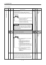
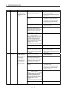
PS10 0005h
PS11
For manufacturer setting
Do not change these values by any means.
0064h
PS12 01F4h
PS13 0000h
PS14 0000h
PS15 0000h
Special setting parameters
PS16
0000h