


4. OPERATION AND FUNCTIONS
4 - 10
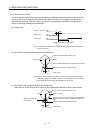
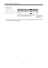
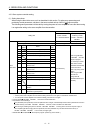
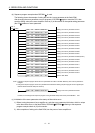
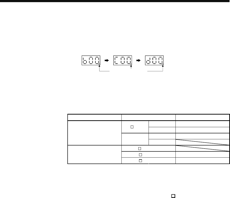
(3) Transition of the servo amplifier display (3-digit 7-segment LED) when detecting magnetic poles
The servo amplifier display (3-digit 7-segment LED) shifts as shown below when the magnetic poles are
detected properly using MR Configurator.
Servo-off status
Detecting
magnetic poles
Magnetic pole
detection
completed
(servo-on status)
Decimal point flickers.
4.3 Operation from the controller
When establishing the absolute position detection system, battery (MR-J3BAT) and the absolute position
storage unit is required.
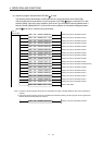
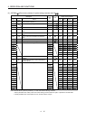
The direct drive servo can be used in combination with the following controllers.
Servo system controller Model Software version (Note)
SV13/SV22 00H or later
Q17 DCPU
SV43 00B or later
Motion controller
SV13/SV22 00G or later
Q170MCPU
SV43
LD77MH
QD74MH 110220000000000-B or later
Positioning module
QD75MH
101120000000000-B or later
Note. Refer to the manual of the each servo system controller for the software version and other
details.
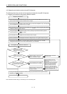
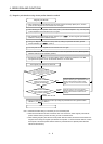
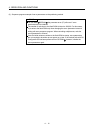
4.3.1 Operation method
The positioning operation from the controller is basically the same as that of MR-J3-
B.
For the system, using the incremental system, however, the magnetic pole detection is automatically performed
at the first servo-on after turning the power on. For this reason, when performing the positioning operation,
configure the sequence which surely confirms the servo-on status as the inter lock condition of the positioning
command.
Also, some parameter settings and home position return varies depending on types of controllers.