


3. SIGNALS AND WIRING
3 - 9
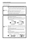
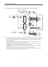
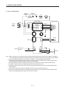
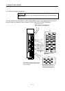
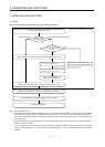
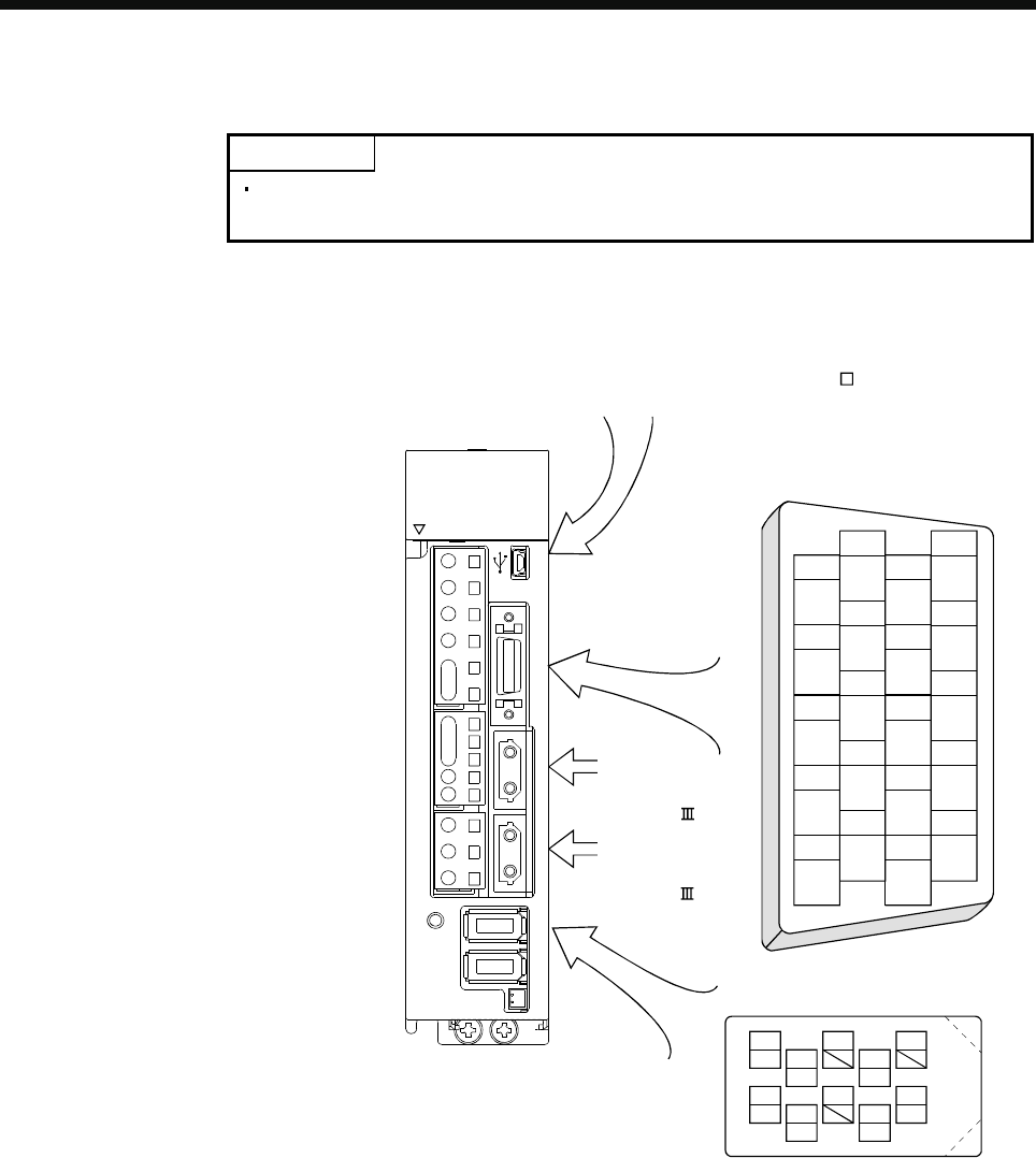
3.4 Connector and signal arrangements
POINT
The pin configurations of the connectors are as viewed from the cable connector
wiring section.
The servo amplifier front view shown is for MR-J3-20B-RJ080W or less. For the appearances and connector
layouts of other servo amplifiers, refer to chapter 7 SERVO AMPLIFIER OUTLINE DRAWINGS.
OPEN
CN4 CN2L CN2 CN1B CN1A CN3 CN5
CHARGE
L
2
U
W
V
D
L
12
L
11
C
P
N
P
1
P
2
L
3
L1
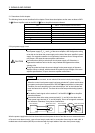
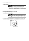
CN5 (USB connector)
Refer to section 11.8 of the MR-J3- B
Servo Amplifier Instruction Manual.
CN3
The frames of the CN2 and CN3 connectors
are connected to the PE (earth) terminal in
the servo amplifier.
CN1A
Connector for the
front axis of CN1A
SSCNET cable.
CN1B
Connector for the
rear axis of CN1B
SSCNET cable.
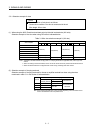
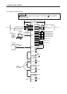
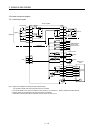
1
2
3
5
4
6
7
9
8
10
11
12
13
14
15
16
17
18
19
20
DI1
MO1
DICOM
LG
DOCOM
DICOM
LZ
DI2
MO2
EM1
LG
MBR
LBR
LA
LB
LZR
LAR
ALM
DI3INP
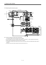
CN2
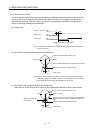
4
MRR
2
LG 8
6
1
P5
5
10
3
MR
7
9
BAT
MDR
MD
The figures of connectors
manufactured by 3M are shown
above. When using any other
connector, refer to section 9.1.2.