


Chapter 3 Installing and Configuring
15
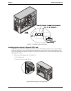
o The optional HP supplied tape drive comes with a 50-to-68-pin adapter to connect to the SCSI
connector on the cable used to connect the tape drive.
· SCSI Drive Addressing
o The drives in the cold swap and hot swap cage are automatically assigned SCSI addresses by the HP
Server.
o The non-hot swap SCSI devices use SCSI IDs from 0 through 15, with the following restrictions:
Ø Narrow SCSI devices must be addressed 0 through 6.
Ø Wide SCSI devices may be addressed 0 through 15, except for ID 7, which is held by the SCSI
controller.
The non-hot swap SCSI devices are all connected to the same cable, which is terminated and
connected to one SCSI controller. Each SCSI device connected to the non-hot swap device
connector must have a unique address.
o The cold swap SCSI back plane is hard wired for SCSI 01238 from bay 1 (bottom) to bay 5
(uppermost cold swap drive bay).
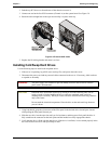
· SCSI Device Installation Order
NOTE The boot drive must be in the bottom slot.
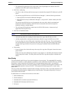
o Add cold swap hard drives starting from the bottom drive cage in the HP Server tc3100.
o Add hot swap hard drives starting from the bottom of the drive cage in the HP Server tc3100.
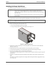
If you are using one or more filler panels, insert them at the top of the cage. These configurations
may use filler panels to close up the front of the cold swap or hot swap mass storage cage. If there
are gaps in the cage, the drives may not receive the proper ventilation and could suffer thermal
damage.
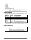
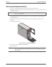
· Filler Panels
o Ensure all empty slots in the cold swap or hot swap drive cage have filler panels inserted to ensure
proper airflow.
If there are fewer drives than the hot swap drive cage supports, a 1-inch filler panel must be inserted
in each empty disk location. The filler panels ensure the drive cage has the proper ventilation and
airflow.
Boot Priority
This section details the HP Server's boot order by highest to lowest priority. The embedded SCSI controller
consists of two channels, A and B. Channel A typically is used to control the external SCSI devices. Channel
B typically is used to control the SCSI hard drives (5) and optional tape back-up drive. On each SCSI
channel, the controller scans for a boot device starting at device ID 0 and works through the ID numbers. The
server's embedded controller is always SCSI ID 7. If an optional SCSI backup tape drive is used it takes
address ID 4.
The server's boot order should be considered when selecting a boot device. This is especially important if you
are installing a board that requires a higher priority in the boot order. The board's boot priority is set by its
slot location in the boot order.
By default the server searches for boot devices in this order:
1. IDE CD-ROM drive
2. Flexible disk drive
3. Embedded SCSI A channel (external SCSI Drives)
4. Embedded SCSI B channel (SCSI Devices)
5. PCI slot 6