


Chapter 5 Error Messages
62
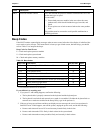
Code Description Problem/Solution
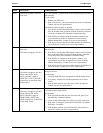
0B3x Processor Module conflict POST has detected the processor modules installed in the server are
not the same type or speed.
To correct this:
2. Ensure both processor modules in the server have the same
product code, which should include the type, heat sink, and
speed.
3. If not, replace one or both to ensure both are the same product
code.
This problem must be corrected to avoid possible malfunction or
reliability problems.
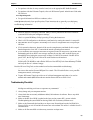
Beep Codes
If the POST routines cannot display messages when an error occurs before the video display is initialized, the
server emits a series of beeps. This means that if on boot you get a blank screen, but hear beeps, you should
refer to Table 5-2 to interpret the beeps.
Beep Codes for Fatal Errors
P = Check and replace processor module
S = Check and replace system board
M = Check and replace memory modules
Table 5-2. Beep Codes
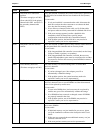
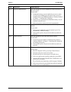
Beep Code Test Failure I/O port 80H Repair
1-2 Check for option ROMs. Checksum failure 98 S
1-2-2-3 BIOS ROM checksum 16 S
1-3-1-1 Test DRAM refresh 20 S, P
1-3-1-3 Test 8742 Keyboard Controller 22 S, P
1-3-4-1 RAM failure on address line xxxx* 2C M, P
1-3-4-3 RAM failure on data bits xxxx* of low byte of memory bus 2E M, P
2-1-2-3 Check ROM copyright notice 46 S
2-2-3-1 Test for unexpected interrupts 58 S
* xxxx indicates the address line or bits that failed.
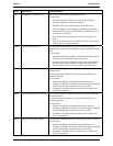
If you still don't see anything and:
1. If you press F1 and nothing happens, confirm the following:
a. The keyboard cable is properly connected to the keyboard and the keyboard port.
b. The keyboard is not locked, and network server mode is not enabled. (If either the keyboard lock or
network server mode was enabled in the Setup Utility, type in the password.)
2. If the server beeps several times and does not display an error message, the server has experienced a
fatal POST error. If this happens, turn off the system, unplug the power cords, and do the following:
a. Remove and reinsert all server PCAs and accessory boards firmly in their slots.
b. Remove and reinsert the CPUs firmly in their sockets in the system board.
c. Remove and reinsert the memory modules firmly and correctly in their sockets.