


93
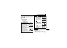
Outline Drawing and Panel Cutting Drawing
6
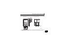
6.2 Outline Drawing and Panel Cutting Drawing
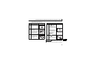
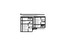
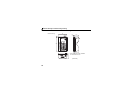
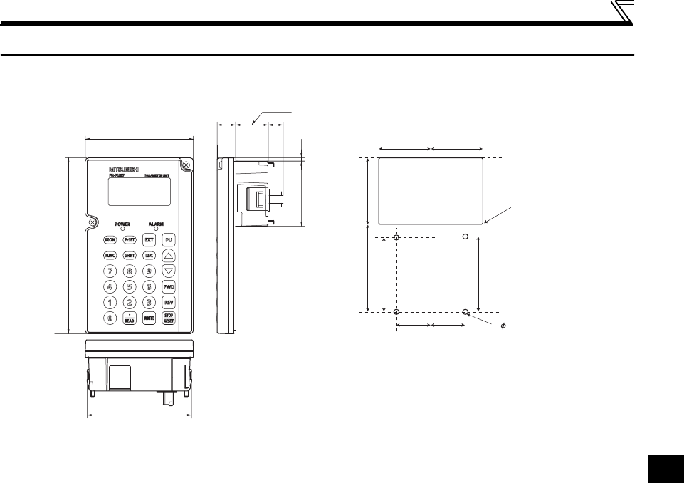
6.2.1 FR-PU07 outline dimension drawings
80.3
(14.2)
2.5
50
(11.45)
25.05
135
83
67
51
40
56.8
57.8
26.5
4-R1
Mounting
hole
4- 4 hole
(Valid screw depth 5.0)
M3 screw *2
26.5
40
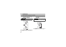
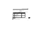
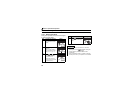
<Outline drawing> <Panel cutting drawing>
*1
*1
*1
*1
*1 When installing the FR-PU07 on the enclosure, etc., remove screws for fixing the FR-PU07 to the inverter or fix the
screws to the FR-PU07 with M3 nuts.
*2 Select the installation screws of which length will not exceed the effective depth of the installation screws threads.
(Unit : mm)