50
Adjustment of the Frequency Setting Signals "Bias" and "Gain"
• Setting of the frequency setting voltage gain
The adjustment of the frequency setting voltage
bias and gain is complete.
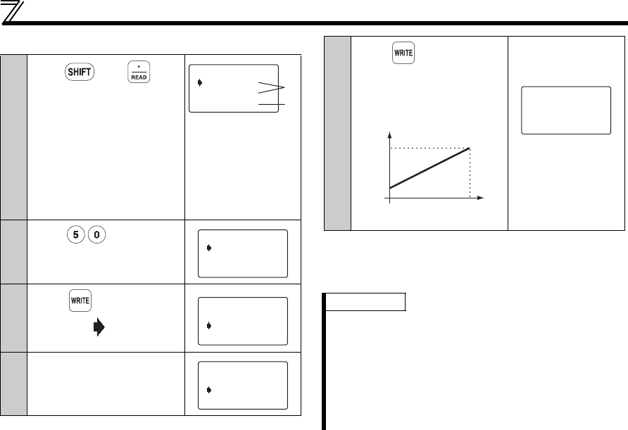
9
Press , then .
The present Pr. 903 setting
appears.
When the set voltage is
changed, the % value also
changes.
The value selected in Pr. 73
(5V in this example) is 100%.
1) The previous
setting is
displayed.
2) The present set
voltage across
terminals 2-5 is
displayed in %.
10
Enter .
11
Press .
The cursor ( ) moves to the
set voltage.
12
Apply a 5V voltage.
In this example, 5V is applied
to set 50Hz for 5V input.
60.00Hz
97.1%
903 Ext2gain
Ext 80.0%
1)
2)
50Hz
97.1%
903 Ext2gain
Ext 80.0%
50.00Hz
97.1%
903 Ext2gain
Ext 80.0%
50.00Hz
97.1%
903 Ext2gain
Ext 80.0%
13
Press .
The gain frequency is set at
50Hz for 5V input.
Setting is completed as
shown below:
The value displayed
may not be just
100.0% in some
cases.
REMARKS
1 The current input (Pr. 904, Pr. 905 ) can also be
adjusted using a similar procedure.
2The Pr. 903 Terminal 2 frequency setting gain remains
unchanged even if the Pr. 20 Acceleration/
deceleration reference frequency setting is changed.
3 A narrow calibration (command) value set using Pr.
902 and Pr. 903 (Pr. 904 and Pr. 905) will result in "Incr
I/P" and disable write.
f
0
V
10Hz
50Hz
5V
(100%)
(0%)
50.00Hz
99.6%
903 Ext2gain
Completed


