49
Adjustment of the Frequency Setting Signals "Bias" and "Gain"
2
(2) Adjust any point by application of voltage to
across terminals 2-5
• Setting of the frequency setting voltage bias
1
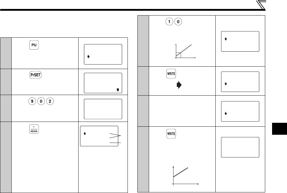
Press .
The frequency setting screen
appears, and operation mode
changes to PU operation mode.
2
Press .
The parameter unit is in the
parameter setting mode.
3
Enter .
4
Press twice.
The present Pr. 902 setting
appears.
When the set voltage is
changed, the % value also
changes.
This example assumes that a
1V voltage is applied.
The value selected in Pr. 73
(5V in this example) is 100%.
1) The previous
setting is
displayed.
2) The present set
voltage across
terminals 2-5 is
displayed in %.
Freq Set
SET 0.00Hz
0~400Hz
SETTING MODE
0~9:Ser Pr.NO.
Select Oper
SETTING MODE
Pr.No.
<READ>
902
5.00Hz
0.5%
902 Ext2bias
Ext 20.0%
1)
2)
5
Enter .
Set the bias frequency at
10Hz.
6
Press .
The cursor ( ) moves to the
set voltage.
7
Apply a 0V voltage.
In this example, 0V is applied
as 10Hz is set for 0V.
(Indicated % on the right
changes.)
8
Press .
The bias frequency is set at
10Hz for 0V input.
Setting is completed as
shown below:
0.0% of analog input
value may not be
displayed in some
cases.
f
0
V
10Hz
1V
10.00Hz
0.5%
902 Ext2bias
EXT 20.0%
10.00Hz
0.5%
902 Ext2bias
Ext - 0.2%
10.00Hz
0.5%
902 Ext2bias
Ext - 0.2%
f
0
V
10Hz
10.00Hz
- 0.2%
902 Ext2bias
Completed


