


55
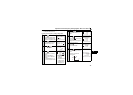
Overview of Function Menu
3
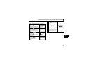
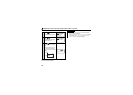
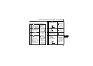
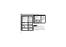
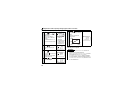
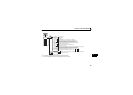
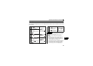
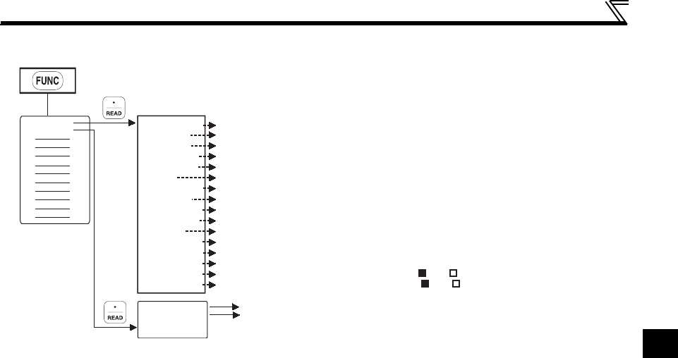
3.1.2 Function menu transition
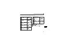
*1 Cannot be monitored for the FR-E700 and FR-D700 series.
*2 Cannot be monitored for the FR-F700 and FR-D700 series.
*3 Can be monitored for the FR-F700 series with the 75K or more.
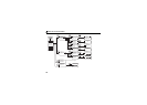
Frequency [Hz]
Current [A]
Voltage [V]
Fault description * The latest 8 faults are displayed
Frequency setting (shows the frequency already set)[Hz]
Running speed (shows the motor speed or moving speed)[r]
Motor torque (torque produced by the motor) [%]
Converter output voltage(DC voltage in converter output) [V]
Regenerative brake duty [%]
Electronic thermal relay function load factor [%]
Output current peak [A]
Converter output voltage peak (maximum value of converter output voltage) [V]
Input power (input side power amount currently used) [kW]
Output power (output side power amount currently used) [kW]
Output signal (ON-OFF states of RUN, FU, etc.) * ON OFF
3
4
5
6
7
8
9
10
11
12
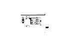
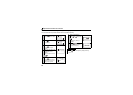
Operation in PU operation mode at running frequency set by numeric keys.
PU Jog operation mode
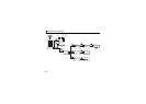
1 Frequency
2 Current
3 Voltage
4 Alarm His
5 F Command
6 RPM
7 Shaft Trq
8 DC Link
9 Br.Duty %
10 Therm O/L
11 Peak I
12 DC Peak V
13 I/P Power
14 O/P Power
15 I/P Signal
16 O/P Signal
2 PU Oper
1 MONITOR
2 JOG:Jogging
1 PU:Directly
Input signal (ON-OFF states of STF, STR, etc.) * ON OFF
*1
*2
*1
*3