


1. Follow the instructions in the Installation, User's, and Maintenance Guide for
your DS4000 storage expansion enclosure to set up and mount the storage
expansion enclosures.
2. Select a cabling topology appropriate for the number of storage expansion
enclosures you will connect to the DS4700 Express. If you are connecting
external storage expansion enclosures to the DS4700 Express, ensure that the
storage expansion enclosures are populated with at least two drives before you
power them on. In addition, you must have at least two drives in the DS4700
Express Storage Subsystem before you power it on.
“DS4700 Express Storage Subsystem drive cabling topologies” describes the
recommended schemes for cabling different numbers of storage expansion
enclosures to the DS4700 Express and to each other (if you are connecting
more than one storage expansion enclosure).
3. After you select the cabling topology for your configuration, follow the cabling
diagram for your chosen topology and perform the steps identified in “DS4700
Express Storage Subsystem and supported storage expansion enclosure drive
cabling schemes” on page 77.
4. If required, set unique enclosure IDs for all storage expansion enclosures that
are cabled to the DS4700 Express. See “DS4000 storage expansion enclosure
ID settings” on page 97, and then refer to your storage expansion enclosure
installation manual for details on setting the enclosure ID.
The DS4700 Express Storage Subsystem locates the drives in the storage
expansion enclosures after you power on the configuration. Always connect power
to the storage expansion enclosures first and then connect power to the DS4700
Express. After you have powered on the configuration, use the DS4000 Storage
Manager client to check the status of the new drives, correct any errors found, and
configure the new drives.
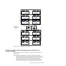
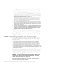
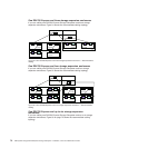
DS4700 Express Storage Subsystem drive cabling topologies
This section provides preferred cabling topologies for cabling storage expansion
enclosures to the DS4700 Express Storage Subsystem. The cabling topologies
include the following:
v “One DS4700 Express and one storage expansion enclosure” on page 72
v “One DS4700 Express and two storage expansion enclosures” on page 72
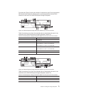
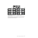
v “One DS4700 Express and three storage expansion enclosures” on page 74
v “One DS4700 Express and four storage expansion enclosures” on page 74
v “One DS4700 Express and up to six storage expansion enclosures” on page 74
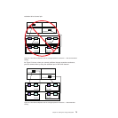
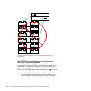
v “One DS4700 Express and two or more storage expansion enclosures in a mixed
configuration” on page 76
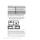
Each example provides redundant paths to the drives. If one of these examples is
suitable for your hardware and application, complete the cabling connections as
described by the graphics. If you have hardware other than what is shown in these
examples to include in your topology, use these examples as a starting point for
creating your specific topology.
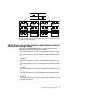
Attention: The DS4700 Express supports the connection of a maximum of six
storage expansion enclosures per redundant drive channel pair. The DS4700
Express supports one redundant drive channel pair.
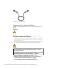
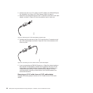
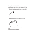
If you are using fiber-optic cables, install SFP modules into the ports that will
receive the cables before installing the cables.
70 IBM System Storage DS4700 Express Storage Subsystem: Installation, User’s and Maintenance Guide