


1. Complete the power-off sequence described in “Turning off the storage
subsystem” on page 134 ensuring that the DS4000 storage subsystem is
turned off before any attached storage expansion enclosures.
Attention:
a. The power switch on the power supply and fan unit does not turn off the
electrical current supplied to the device. The DS4700 Express Storage
Subsystem might also have more than one connection to dc power. To
remove all electrical current from the device, ensure that all dc power cords
are disconnected from the power supply and fan unit dc input connectors.
b. For a DS4700 Express Storage Subsystem with dc power supply and fan
units only, turn off all of the attached disconnect devices. IBM recommends
that you use the disconnect device to remove power before disconnecting
the dc power cord.
2. Label and remove the power cords from the power supply and fan units of the
DS4700 Express Storage Subsystem.
3. Label the fibre channel cables that are attached to the rear of the controllers.
Labeling the cables simplifies the re-cabling process.
4. Remove the fibre channel cables that are attached to the rear of the
controllers.
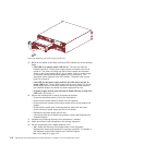
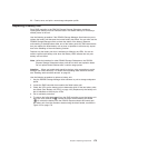
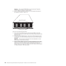
5. Remove both controllers. To remove them do the following:
a. Squeeze the controller latch and pull the lever open 90° (so that the lever
is horizontal) to release the controller from the latch. The controller latch is
a coral colored tab on the lever.
Note: The lever rotates upward or downward 90°, depending on whether
the controller you are removing is the right or left controller CRU.
b. Slowly pull the lever away from the storage subsystem chassis to remove
the controller from the controller bay, as shown in Figure 21 on page 42.
(Remove the controllers from the chassis and place it on electrostatic
discharge (ESD) protected surface.)
c. Repeat steps 5a and 5b for the other controller.
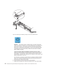
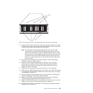
6. Remove both power supply and fan units. To remove them, do the following:
a. Squeeze the latch and pull the lever open 90° (so that the lever is
horizontal) to release the power supply and fan unit from the latch. The
latch is a coral colored tab on the lever.
b. Slowly pull the lever away from the chassis to remove the power supply
and fan unit, as shown in Figure 22 on page 43. (Remove the power
supply and fan unit from the chassis and place it on ESD protected
surface.)
Note: The lever rotates upward or downward 90°, depending on whether
the power supply and fan unit you are removing is in the right or left
power supply and fan unit bay.
c. Repeat steps 6a and 6b for the other power supply and fan unit.
7. Remove the Telco bezel if it is installed. See “Removing and replacing a bezel”
on page 150 for instructions.
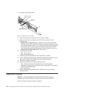
8. Label the Enhanced Disk Drive Module (E-DDM) CRUs so you know their
physical location in the midplane.
9. Remove the E-DDM CRUs and any blank drive CRUs if the storage subsystem
has them. See “Removing an E-DDM” on page 45 for instructions. Place
E-DDMs on ESD protected surface.
Chapter 5. Replacing components 179