


– For optimum performance, never insert a E-DDM into a storage subsystem
without first confirming the drive firmware level. In the event of a drive
firmware mismatch, schedule down time as soon as possible to upgrade the
drive firmware to the same version. For information about supported drive
firmware versions, refer to the DS4000 Support Web site:
www.ibm.com/systems/support/storage/disk
– Use of non-supported drives in the drive modules can cause the storage
subsystem to fail.
– In configurations with mixed storage expansion enclosures, all storage
expansion enclosures on a fibre loop must be operating at the same interface
speed.
– Ensure that the speed of the E-DDM CRU you are adding is supported in the
storage subsystem. For example, do not install a 2 Gbps E-DDM CRU in a
storage subsystem that supports only 4 Gbps E-DDMs.
– E-DDM CRUs are not interchangeable between EXP710 and EXP810 storage
expansion enclosures.
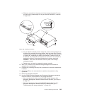
– After you remove a E-DDM CRU, wait 70 seconds before replacing or
reseating it to allow it to properly spin down. Failure to do so may cause
undesired events.
Attention
Before powering on the DS4700 Express Storage Subsystem, it must be
populated with at least two E-DDMs. If at least two E-DDMs are not
installed in each attached storage expansion enclosure or DS4700 Express
Storage Subsystem, when you power on the DS4700 Express and its
attached storage expansion enclosures, your standard storage partition key
might be lost and must be regenerated using instructions on the IBM
DS4000 Solutions and Premium Features Web site:
https://www-912.ibm.com/PremiumFeatures/
In addition, the resulting insufficient load to the enclosure power supplies
might cause them to intermittently appear as failed, falsely indicating the
power supplies are bad. All drives in the DS4700 Express Storage
Subsystem and the connected storage expansion enclosure or enclosures
must contain no prior configuration data.
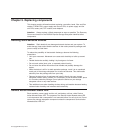
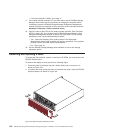
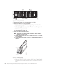
v E-DDM CRU labels: A label is provided on the front of each E-DDM. Use this
label to record the location information for each E-DDM before you remove it.
Ensure that you keep track of the E-DDMs and their corresponding bays. Also,
record the location information in Table 55 on page 194. If you install an E-DDM
in the wrong bay, you might lose data.
v E-DDM LEDs: Each E-DDM CRU tray has two associated LEDs, a green Activity
LED and an amber Fault LED. These LEDs indicate the status for that drive. See
Table 49 for the E-DDM LED states and descriptions.
v E-DDM CRUs are not interchangeable between the DS4700 Express and other
DS4000 storage subsystems.
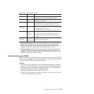
Table 49. Drive LED activity
LED LED state Descriptions
Activity LED Flashing green The green LED flashes to indicate fibre-channel activity to
the drive.
152 IBM System Storage DS4700 Express Storage Subsystem: Installation, User’s and Maintenance Guide