Tables
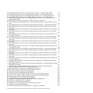
1. Where to find DS4000 installation and configuration procedures .............xxii
2. Description of Figure 2 on page 10 ........................10
3. Description of Figure 3 on page 10 ........................10
4. Description of Figure 4 on page 13 ........................13
5. Description of Figure 5 on page 13 ........................13
6. DC power supply and fan unit description for DS4700 Express model 70 ..........15
7. DC power supply and fan unit description for DS4700 Express model 72 ..........16
8. Description of Figure 10 on page 18........................18
9. Filter and filter retainer description ........................20
10. DS4700 Express weights ............................23
11. DS4700 Express component weights .......................23
12. DS4700 Express shipping carton dimensions ....................23
13. Temperature and humidity requirements for storage subsystem when in storage or in transit 24
14. Temperature and humidity requirements for storage subsystem in a typical Information Technology
(IT) or office environment............................24
15. Temperature and humidity requirements for storage subsystem in a Telco/NEBS-3 compliant
environment ................................24
16. DS4700 Express altitude ranges .........................25
17. DS4700 Express power and heat dissipation ....................26
18. Random vibration power spectral density ......................26
19. DS4700 Express sound levels ..........................26
20. DS4700 Express ac power requirements ......................27
21. DS4700 Express dc power requirements ......................27
22. Description of Figure 32 on page 56........................56
23. DS4700 Express Storage Subsystem (Model 70) host ports and drive channels........71
24. DS4700 Express Storage Subsystem (Model 72) host ports and drive channels........71
25. DS4700 Express drive ports connected to EXP810 ESM ports labeled 1B ..........79
26. DS4700 Express drive ports connected to 14-drive storage expansion enclosure ESM In and Out
ports ...................................80
27. Description of Figure 76 ............................95
28. Description of Figure 77 ............................96
29. Description of Figure 78 ............................97
30. Recommended enclosure ID settings scheme when connecting a DS4700 to EXP710s or
EXP100s..................................98
31. Possible combinations of 14-drive and 16-drive storage expansion enclosures per redundant
drive/channel loop pair in a DS4700 Express configuration ...............99
32. DS4700 Express Storage Subsystem (Model 72) location of host ports on controllers .....101
33. DS4700 Express Storage Subsystem (Model 72) location of host ports on controllers .....101
34. Description of Figure 61............................102
35. Description of Figure 62............................104
36. DS4700 Express Storage Subsystem (Model 70) location of host ports on controllers .....105
37. DS4700 Express Storage Subsystem (Model 72) location of host ports on controllers .....105
38. DC power supply connector - PIN descriptions ...................114
39. DC power source wiring descriptions .......................115
40. Power supply and fan unit LEDs.........................126
41. DC power supply and fan unit LEDs .......................127
42. Front LEDs and controls ...........................128
43. Battery unit LEDs ..............................129
44. Rear controller LEDs, controls, and connectors ...................130
45. Host and drive channel LED definitions ......................132
46. Numeric display diagnostic codes ........................133
47. Description of Figure 103 on page 141 ......................141
48. Battery unit LEDs ..............................143
© Copyright IBM Corp. 2010 xiii


