


9. Turn off the dc power supply switch, set disconnect devices to the OFF
position, and then unplug the power cord from the failed dc power supply and
fan unit.
Attention:
a. IBM recommends that you use the disconnect device to remove power
before disconnecting the dc power cord.
b. The power switch on the dc power supply and fan unit does not turn off the
electrical current supplied to the device. The DS4700 Express Storage
Subsystem power supply and fan unit might also have more than one
connection to dc power. To remove all electrical current from the device,
ensure that all dc power cords are disconnected from the power supply
and fan unit dc input connectors.
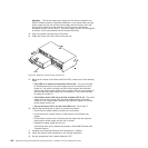
10. Squeeze the latch and pull the lever open 90° (so that the lever is horizontal)
to release the dc power supply and fan unit from the latch. The latch is a coral
colored tab on the lever.
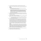
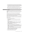
11. Slowly pull the lever away from the chassis to remove the dc power supply and
fan unit, as shown in Figure 115 on page 174.
Note: The lever rotates upward or downward 90°, depending on whether the
dc power supply and fan unit you are removing is in the right or left dc
power supply and fan unit bay.
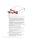
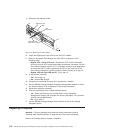
12. Slide the new unit into the empty slot. As you slide the dc power supply and
fan unit into the empty slot, make sure the guide pins on the side of the dc
power supply and fan unit fit into the notches. After the guide pins fit into the
notches and dc power supply and fan unit fits snugly into the slot, push the
lever downward or upward 90° to fully latch the dc power supply and fan unit
into place, depending on whether you are inserting the dc power supply and
fan unit into the right or left dc power supply and fan unit bay. Then gently
push the front of the dc power supply and fan unit to ensure that it is fully
seated.
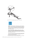
Attention: The left and right dc power supplies are seated in the DS4700
Express chassis in opposite orientations. If you cannot fully insert the dc power
supply and fan unit into the dc power supply and fan unit bay, flip it 180° and
reinsert it. Make sure that the levers lock into place in the storage subsystem
chassis. Do not force fit. The dc power supply and fan unit is designed to
prevent it from being inserted into the chassis incorrectly.
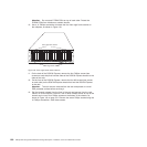
13. Plug in the power cord, turn on any attached disconnect devices, and turn on
the power to the dc power supply and fan unit.
14. Check the Power and Fault LEDs on the new unit.
Chapter 5. Replacing components 173