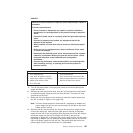
DANGER
Electrical current from power, telephone, and communication cables is
hazardous.
To avoid a shock hazard:
v Do not connect or disconnect any cables or perform installation,
maintenance, or reconfiguration of this product during an electrical
storm.
v Connect all power cords to a properly wired and grounded electrical
outlet.
v Connect to properly wired outlets any equipment that will be
attached to this product.
v When possible, use one hand only to connect or disconnect signal
cables.
v Never turn on any equipment when there is evidence of fire, water,
or structural damage.
v Disconnect the attached power cords, telecommunications systems,
networks, and modems before you open the device covers, unless
instructed otherwise in the installation and configuration
procedures.
v Connect and disconnect cables as described in the following table
when installing, moving, or opening covers on this product or
attached devices.
To Connect: To Disconnect:
1. Turn everything OFF.
2. First, attach all cables to devices.
3. Attach signal cables to connectors.
4. Attach power cords to outlet.
5. Turn device ON.
1. Turn everything OFF.
2. First, remove power cords from outlet.
3. Remove signal cables from connectors.
4. Remove all cables from devices.
9. Turn off the power switch, and unplug the power cord from the failed power
supply and fan unit.
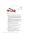
10. Squeeze the latch and pull the lever open 90° (so that the lever is horizontal)
to release the power supply and fan unit from the latch. The latch is a coral
colored tab on the lever.
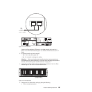
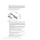
11. Slowly pull the lever away from the chassis to remove the power supply and
fan unit, as shown in Figure 114 on page 168.
Note: The lever rotates upward or downward 90°, depending on whether the
power supply and fan unit you are removing is in the right or left power
supply and fan unit bay.
12. Slide the new unit into the empty slot. As you slide the power supply and fan
unit into the empty slot, make sure the guide pins on the side of the power
supply and fan unit fit into the notches. After the guide pins fit into the notches
and power supply and fan unit fits snugly into the slot, push the lever
downward or upward 90° to fully latch the power supply and fan unit into place,
depending on whether you are inserting the power supply and fan unit into the
right or left power supply and fan unit bay. Then gently push the front of the
power supply and fan unit to ensure that it is fully seated.
Chapter 5. Replacing components 167


