


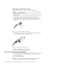
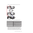

Table 24. DS4700 Express Storage Subsystem (Model 72) host ports and drive
channels (continued)
Number Description
3 Drive Channel 1 - Port 2 on Controller A
Drive Channel 2 - Port 2 on Controller B
4 Drive Channel 1 - Port 1 on Controller A
Drive Channel 2 - Port 1 on Controller B
5 Host Port 4
6 Host Port 3
7 Host Port 2
8 Host Port 1
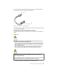
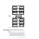
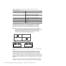
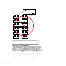
One DS4700 Express and one storage expansion enclosure
If you are cabling one DS4700 Express Storage Subsystem to one storage
expansion enclosure, Figure 51 shows the recommended cabling topology.
Note: Figure 51 illustrates the drive channel connections between the DS4700
Express and the storage expansion enclosures. Do not use Figure 51 as the
cabling diagram. Follow the instructions in “DS4700 Express Storage
Subsystem and supported storage expansion enclosure drive cabling
schemes” on page 77 for specific cabling instructions.
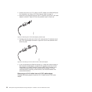
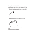
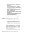
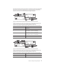
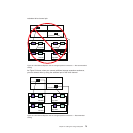
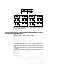
One DS4700 Express and two storage expansion enclosures
If you are cabling one DS4700 Express Storage Subsystem and two storage
expansion enclosures, Connect one storage expansion enclosure per controller
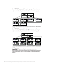
drive port as shown in Figure 52 on page 73. Figure 53 on page 73 shows that you
can also connect two expansion enclosures together behind a single controller drive
port. Although this is technically correct, use the topology as shown in Figure 52 on
page 73.
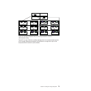
As Figure 52 on page 73 shows, when you connect additional storage expansion
enclosures, you can connect them by continuing the connection from the existing
Left ESM
Right ESM
Controller A
Controller B
1
2
2
1
ds470043
Figure 51. One DS4700 Express and one storage expansion enclosure — Recommended
cabling
72 IBM System Storage DS4700 Express Storage Subsystem: Installation, User’s and Maintenance Guide