


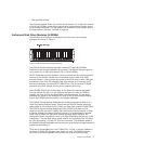
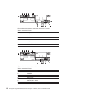
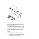
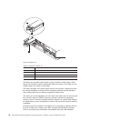

Table 4. Description of Figure 4
Number Description
1 Power supply and fan unit A
2 Power supply and fan unit B
3 Power connector
4 Power switch
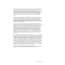
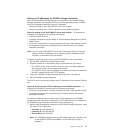
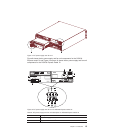
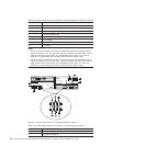
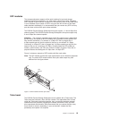
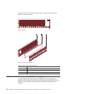
Table 5. Description of Figure 5
Number Description
1 Power supply and fan unit A
2 Power supply and fan unit B
3 Power connector
4 Power switch
Figure 6 on page 14 shows a power supply and fan unit and the airflow through the
storage subsystem.
ds470040
3
2
3
4
1
4
Figure 4. Power supply and fan unit components for DS4700 Express model 70
ds470041
3
2
3
4
1
4
Figure 5. Power supply and fan unit components for DS4700 Express model 72
Chapter 1. Introduction 13