


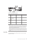
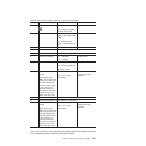

Table 44. Rear controller LEDs, controls, and connectors (continued)
Number LED Normal Status Problem Status
3 Cache Active
On - Data is in cache
Off - Caching is turned
off. No data in cache
Not applicable
4 Diagnostic On - Seven-segment
LEDs indicate diagnostic
code
Off - Seven-segment
LEDs indicate enclosure
ID
Not applicable
5 Heartbeat Blinking Off
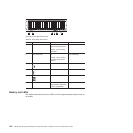
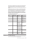
6 Host Channel Speed - L1 See Table 45 on page 132.
7 Host Channel Speed - L2 See Table 45 on page 132.
8 Ethernet Link Speed On - 100 Mbps
Off - 10 Mbps
Not applicable
9 Ethernet Link Activity On - link established
Off - no link established
Blinking - activity
Not applicable
10 Drive Channel Port
Bypass
(One LED per port)
Note: The drive channel
consists of two FC ports.
This LED indicates the
drive port bypass status
of one of the two FC
ports that comprise a
drive channel. The LED
marked 13 shows the
status of the other port.
Off
(Also off if no SFP
connected)
On - No valid device
detected and port is
bypassed
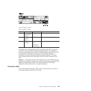
11 Drive Channel Speed - L1 See Table 45 on page 132.
12 Drive Channel Speed - L2 See Table 45 on page 132.
13 Drive Channel Port 2
Bypass
(One LED per port)
Note: The drive channel
consists of two FC ports.
This LED indicates the
drive port bypass status
of one of the two FC
ports that comprise a
drive channel. The LED
marked 10 shows the
status of the other port.
Off
(Also off if no SFP
connected)
On - No valid device
detected and port is
bypassed
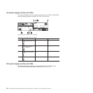
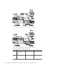
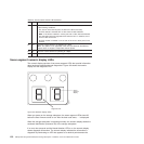
The L1 and L2 LEDs for each host and drive channel combine to indicate the status
and the operating speed of each host and drive channel.
Chapter 4. Operating the storage subsystem 131