


Complete the following steps to replace the dc power supply and fan units that you
removed before the installation:
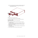
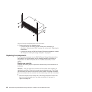
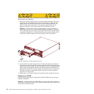
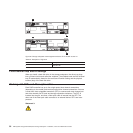
1. Slide one dc power supply and fan unit into the storage subsystem. Be sure to
replace the dc power supply and fan unit so that the lever on each dc power
supply and fan unit opens toward the interior of the storage subsystem, as
shown in Figure 29. Do not force fit. The dc power supply and fan unit is
designed to prevent it from being inserted into the chassis incorrectly.
Attention: Be sure that the lever is pulled straight out as you slide the dc
power supply and fan unit into the storage subsystem, as shown in Figure 29.
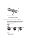
The left and right dc power supplies are seated in the DS4700 Express chassis
in opposite orientations. If you cannot fully insert the dc power supply and fan
unit into the dc power supply and fan unit bay, flip it 180° and reinsert it.
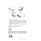
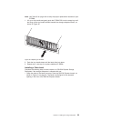
2. As you slide the dc power supply and fan unit into the empty slot, make sure
the guide pins on the side of the dc power supply fit into the notches along the
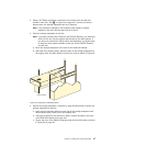
sides of the dc power supply bay. After the guide pins fit into the notches and dc
power supply fits snugly into the slot, push the lever upward or downward 90°
depending on whether the dc power supply is inserted in the left or right bay to
fully latch it into place. Then gently push the front of the dc power supply to
ensure that it is fully seated.
3. Repeat step 1 and step 2 to replace the second dc power supply and fan unit.
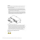
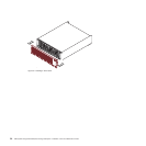
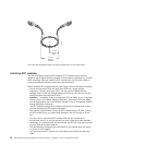
Replacing an E-DDM
Complete the following steps to replace the hot-swap E-DDMs that you removed
before the installation.
Attention: After you remove a E-DDM CRU, wait 70 seconds before replacing or
reseating the E-DDM CRU to allow the E-DDM to properly spin down. Failure to do
so may cause undesired events.
ds470071
Figure 29. Replacing a dc power supply and fan unit
52 IBM System Storage DS4700 Express Storage Subsystem: Installation, User’s and Maintenance Guide