


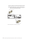
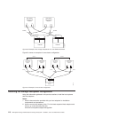
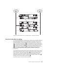

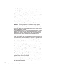

Dual-level redundant dc cabling
In a dual-level redundancy dc cabling scheme, both dc power connectors in each of
the dc power supply and fan units are connected to a dc power source. You will
need two additional dc power cables (IBM Option P/N 42D3329) to cable in this
way. The dc power connectors A1 (5) are connected to the left dc power source
(1) and dc power connectors A2 (7) are connected to the right dc power source
(2). dc power connectors B1 (6) are connected to the right dc power source
(2) and dc power connectors B2 (8) are connected to the left dc power source
(1). For maximum protection, connect dc power connectors A2 and B2 to a
different set of dc power sources than dc power connectors A1 and B1 are
connected to.
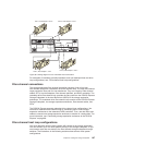
This cabling scheme protects against certain combinations of dual failures in the dc
power supply connections such as a failed dc source and dc power supply and fan
unit. For example, if the left dc power source (1) and the right side dc power
supply and fan unit failed, the DS4700 Express Storage Subsystem remains
operational because the dc power is supplied from the right dc power source (2)
through the left dc power supply connector A2 (7).
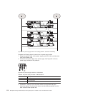
Figure 93 on page 114 illustrates dual-level cabling.
5
6
4
3
1
2
4
5
6
5
6
ds470094
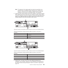
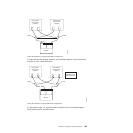
Figure 92. DC power supply and fan unit cabling scheme - single-level redundancy
Chapter 3. Cabling the storage subsystem 113