


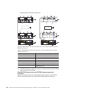


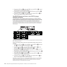
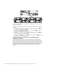
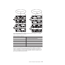

Perform the following steps to create the recommended cabling scheme shown in
Figure 70:
1. Connect the OUT port (2) on the left ESM in the first EXP710 (3) to the IN
port (1) on the left ESM in the third EXP710 (5).
2. Connect the IN port (1) on the right ESM in the third EXP710 (5)tothe
OUT port (2) on the right ESM in the first EXP710 (3).
3. Connect the IN port (1) on the left ESM in the first EXP710 (3)toport2of
drive channel 1 on the DS4700 Express.
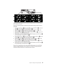
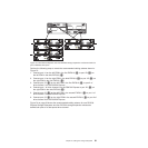
4. Connect the OUT port (2) on the left ESM in the third EXP710 (5)tothe
IN port (1) on the left ESM in the fifth EXP710 (7).
5. Connect the IN port (1) on the right ESM in the fifth EXP710 (7)tothe
OUT port (2) on the right ESM in the third EXP710 (5).
6. Connect port 1 of drive channel 2 on the DS4700 Express to the OUT port
(2) on the right ESM in the fifth EXP710 (7).
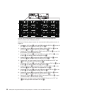
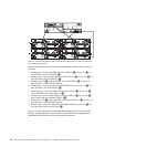
7. Connect the OUT port (2) on the left ESM in the second EXP710 (4)tothe
IN port (1) on the left ESM in the fourth EXP710 (6).
8. Connect the IN port (1) on the right ESM in the fourth EXP710 (6)tothe
OUT port (2) on the right ESM in the second EXP710 (4).
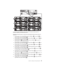
9. Connect the OUT port (2) on the left ESM in the fourth EXP710 (6)tothe
IN port (1) on the left ESM in the sixth EXP710 (8).
10. Connect the IN port (1) on the right ESM in the sixth EXP710 (8)tothe
OUT port (2) on the right ESM in the fourth EXP710 (6).
11. Connect the IN port (1) on the left ESM in the second EXP710 (4) to port
1 of drive channel 1 on the DS4700 Express.
12. Connect port 2 of drive channel 2 on the DS4700 Express to the OUT port
(2) on the right ESM in the sixth EXP710 (8).
ds470054
2
1
2
1
2
1
3
4
5
2
1
6
2
1
2
1
8
7
DS4700
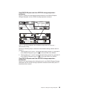
Figure 70. One DS4700 Express and a maximum of six EXP710 storage expansion
enclosures behind a pair of DS4700 drive ports
88 IBM System Storage DS4700 Express Storage Subsystem: Installation, User’s and Maintenance Guide