


Save all packing materials in the event you need to return the new battery unit.
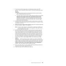
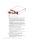
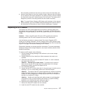
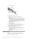
8. Insert the new battery unit into the controller chassis. Make sure the new battery
unit is inserted in the correct orientation in the battery unit bay. Press the battery
unit fully into the bay until it clicks into place. Do not force fit. The battery unit is
designed to prevent it from being inserted into the chassis incorrectly.
Note: The green Battery Charging LED flashes until the battery is fully charged.
9. Reset the battery age in the DS4000 Subsystem Management window. Refer to
the online help for instructions on how to reset the battery age, if required.
Replacing an SFP module
The speed of the SFP module determines the maximum operating speed of the
fibre channel port in which the SFP is installed. For example, a 2-Gbps SFP that is
plugged into a 4-Gbps-capable port will limit the speed of that port to a maximum of
2 Gbps.
Attention: Refer to the FRU option P/N on the SFP to identify the maximum
operating speed of the SFP and to request the correct FRU replacement.
Use the following procedure to replace a Small Form-factor Pluggable (SFP)
module on the storage subsystem. The SFP module shown in this procedure might
look different from those you are using, but the difference will not affect functionality.
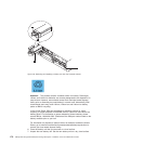
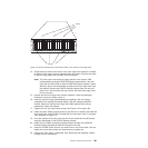
Figure 117 on page 178 illustrates installing an SFP module.
Electrostatic discharge can damage sensitive components. To prevent electrostatic
discharge damage to the storage subsystem, use proper antistatic protection when
handling components.
To replace an SFP module, do the following:
1. Use the DS4000 Storage Manager client software to print a new storage
subsystem profile.
2. Using the Recovery Guru, identify the failed component that needs to be
replaced.
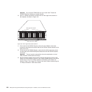
3. Check the Fault LEDs to locate the failed SFP module. If a fault is detected,
the amber Fault LED is on.
Attention: Potential loss of data access - To prevent loss of access to
data, remove only the SFP module that has a failed status in the storage
management software and has Port Bypass LED lit.
4. Put on antistatic protection.
5. Unpack the new SFP module. Verify that it is the same type of module you are
replacing. If it is not, contact IBM Customer and Technical Support.
Attention: The speed of the SFP module determines the maximum operating
speed of the fibre channel port in which the SFP is installed. For example, a
2-Gbps SFP that is plugged into a 4-Gbps-capable port will limit the speed of
that port to a maximum of 2 Gbps.
Attention: Handle and install fiber-optic cables properly to avoid degraded
performance or loss of communications with devices. For specific handling
guidelines, see “Handling fibre-optic cables” on page 57.
6. Disconnect the interface cables from the SFP module.
7. Remove the failed SFP module from the controller.
8. Install the new SFP module into the controller.
Chapter 5. Replacing components 177