


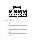


One DS4700 Express and one EXP710 storage expansion
enclosure
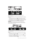
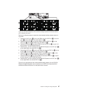
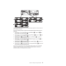
Figure 66 shows the recommended cabling scheme for one DS4700 Express
Storage Subsystem and one EXP710 storage expansion enclosure.
Perform the following steps to create the recommended cabling scheme as shown
in Figure 66:
1. Connect either port 2 or port 1 of the dual-ported drive channel 1 in controller A
of the DS4700 Express to the IN port (1) on the left ESM of the EXP710.
2. Connect either port 1 or port 2 of the dual-ported drive channel 2 in controller B
of the DS4700 Express to the OUT port (2) on the right ESM of the EXP710.
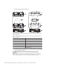
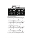
One DS4700 Express and two EXP710 storage expansion
enclosures
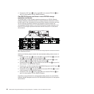
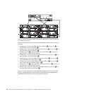
Figure 67 shows the recommended cabling scheme for one DS4700 Express
Storage Subsystem and two EXP710 storage expansion enclosures behind both
ports of a dual-ported drive channel.
Perform the following steps to create the recommended cabling scheme shown in
Figure 67:
1. Connect port 2 of drive channel 1 on the DS4700 Express to the IN port (1)
on the left ESM on the first EXP710 (3).
ds470034
2
1
DS4700
EXP100
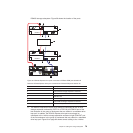
Figure 66. One DS4700 Express and one EXP710 storage expansion enclosure —
Recommended cabling
ds470037
2
1
2
1
3
4
DS4700
EXP100 EXP100
Figure 67. One DS4700 Express and two EXP710 storage expansion enclosures behind a
pair of DS4700 drive ports
Chapter 3. Cabling the storage subsystem 85