


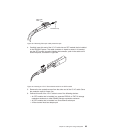
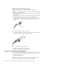
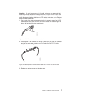
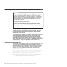
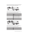
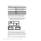
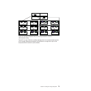

Figure 49 and Figure 50 show the locations of controllers A and B, the single-ported
fibre-channel host channels, Ethernet ports, and dual-ported fibre-channel drive
channels at the back of the DS4700 Express Storage Subsystem.
Table 23 provides a list of the drive channels that are associated with each of the
controllers on the DS4700 Express Storage Subsystem (model 70).
Table 23. DS4700 Express Storage Subsystem (Model 70) host ports and drive channels
Number Description
1 Controller A
2 Controller B
3 Drive Channel 1 - Port 2 on Controller A
Drive Channel 2 - Port 2 on Controller B
4 Drive Channel 1 - Port 1 on Controller A
Drive Channel 2 - Port 1 on Controller B
5 Host Port 2
6 Host Port 1
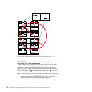
Table 24 provides a list of the drive channels that are associated with each of the
controllers on the DS4700 Express Storage Subsystem (model 72).
Table 24. DS4700 Express Storage Subsystem (Model 72) host ports and drive channels
Number Description
1 Controller A
2 Controller B
ds470013
3
4
5
6
2
3
4
5
6
1
Figure 49. DS4700 Express Storage Subsystem (Model 70) ports and controllers
ds470014
2
3
4
5
6
1
8
7
3
4
5
6
8
7
Figure 50. DS4700 Express Storage Subsystem (Model 72) ports and controllers
Chapter 3. Cabling the storage subsystem 71