


20. Create, save, and print a new storage subsystem profile.
Replacing a battery unit
Each RAID controller in the DS4700 Express Storage Subsystem contains a
rechargeable battery unit that maintains data in the cache memory for three days
without power to the unit.
Use the following procedure if the DS4000 Storage Manager client instructs you to
replace the battery unit because the current battery has failed. You can also use the
DS4000 Storage Manager client to check the status of the battery. Because
write-caching is disabled when either one of the battery units fail, IBM recommends
that you replace the failed battery unit as soon as possible to minimize any impact
due to the disabling of the write-caching function.
Replace only the battery unit that is indicated as failed by the LEDs. You do not
need to replace both battery units when the Battery LEDs indicate that only one
battery unit has failed.
Note: Unlike the batteries for other DS4000 Storage Subsystems, the DS4700
Express Storage Subsystem battery units do not have set expiration dates.
Do not replace these batteries after a certain usage period.
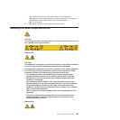
Attention: When you handle static-sensitive devices, take precautions to avoid
damage from static electricity. For details about handling static-sensitive devices,
see “Handling static-sensitive devices” on page 33.
Use the following procedure to replace a battery unit.
1. Use the DS4000 Storage Manager client software to print a storage subsystem
profile.
2. Locate the RAID controller that contains the failed battery unit.
3. Check the LEDs on the battery units to determine which of the two battery units
has failed. (See “Battery unit LEDs” on page 128.) Replace only the battery unit
that is indicated as failed by the LEDs.
4. Put on antistatic protection.
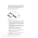
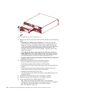
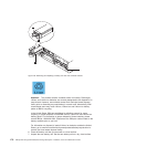
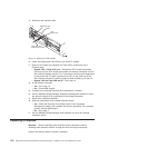
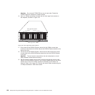
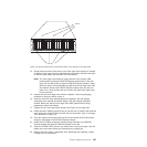
5. To remove the failed battery unit from the RAID controller, press the battery unit
latch (the coral colored tab3) toward the black colored battery pull handle
(4) to unlatch the battery from the DS4700 Express chassis and slowly pull
the battery unit from the controller chassis using the black handle, as shown in
Figure 116 on page 176.
Chapter 5. Replacing components 175