


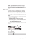

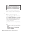
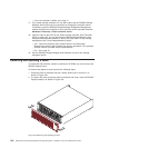
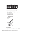

a. Slide one controller into the empty slot in the storage subsystem. Be sure
that the lever is pulled straight out as you slide the controller in, as shown
in Figure 108.
b. As you slide the controller into the empty slot, make sure the guide pins on
the side of the controller fit into the notches. After the guide pins fit into the
notches and the controller fits snugly into the bay, push the lever downward
or upward 90°, depending on whether the controller is inserted in the A or
B controller bay to fully latch it into place. Do not force fit. The controller is
designed to prevent it from being inserted into the chassis incorrectly.
Attention: Make sure that the levers lock into place in the storage
subsystem chassis.
c. Repeat step a and step b to replace the second controller.
12. Wait up to 5 minutes for the DS4000 Storage Manager client software to
recognize the new controller.
13. Complete any remaining Recovery Guru procedures for controller replacement,
if needed.
14. Check the LEDs on the new controller to verify that the controller is fully
operational.
15. Remove the antistatic protection.
16. Use the DS4000 Storage Manager client Subsystem Management window to
check the status of all components in the storage subsystem.
v If the new controller is online and the DS4000 Storage Manager client
Subsystem Management window indicates normal operation, go to step 19
on page 150.
v If the new controller is online and the DS4000 Storage Manager client
Subsystem Management window indicates a problem status, go to
“Troubleshooting the storage subsystem ” on page 124.
Lever
Guide pin
Notch
Figure 108. Installing a controller
Chapter 5. Replacing components 149