


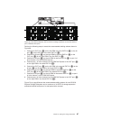
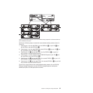
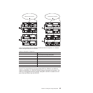
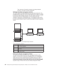

Table 27. Description of Figure 76
Number Description
1 DS4700 Express Storage Subsystem
2 EXP100
3 EXP810
4 IN port
5 OUT port
6 Port 1B
7 Port 1A
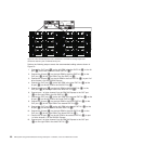
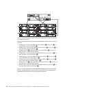
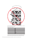
Figure 77 on page 96 shows an unacceptable EXP710, EXP810, and EXP100
intermix configuration in a DS4700 Express Storage Subsystem environment. The
cabling is unacceptable because storage subsystem controller is cabled to the IN
port on the left ESM of the first EXP100.
ESM B
ESM A
ESM BESMA
ESM BESMA
ESM BESM A
ESM B
ESM A
ESM BESM A
Out
ESM B
ESMA
ESM B
ESMA
1 1
22
2
3
3
4
5
4
5
4
45 5
6
7
6
7
6
7
7
6
6
7
7
6
6
7
7
6
4
45 5
4 4
5 5
exp100810a
DS4000 Storage Subsystem
EXP100
EXP100
EXP100
EXP100
EXP810
EXP810
EXP810
EXP810
DS4000 Storage Subsystem
Figure 76. Acceptable EXP710, EXP810 and EXP100 intermix configuration in a DS4700
Express Storage Subsystem environment
Chapter 3. Cabling the storage subsystem 95