


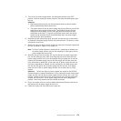
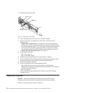


14. Grasp the blue handle in the center of the front cage frame and pull it outward
to slide the front cage frame out approximately two inches. Grab the two sides
of the front cage frame and remove it from the chassis.
Note: The front cage frame might be tightly secured in the chassis. IBM
recommends mounting the DS4700 Express chassis back in the rack
using the four M5 screws to hold the DS4700 Express chassis in place
while you pull on the blue handle to separate the front cage frame from
the chassis. Remove the DS4700 Express chassis from the rack and
place it on a level surface after you remove the failed front cage frame
for the next step.
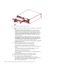
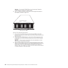
15. Unpack the new front cage frame with the midplane. Save the packaging
materials in case you need to return it.
16. Insert the new front cage plane/midplane by aligning it with the storage
subsystem front opening and slowly sliding it into the storage subsystem
chassis. Make sure that the front cage frame EMC gaskets do not snag
between the frame and chassis.
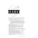
17. Tighten the four front cage frame screws. See Figure 118 on page 180.
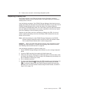
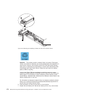
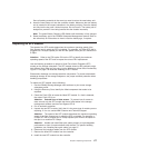
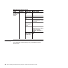
18. Install the seven Phillips screws (three on top and four on bottom) that hold the
front cage frame to the EXP810 chassis that you removed in step 13 on page
180, as shown in Figure 119.
19. Push the chassis all the way back into the rail and install the four M5 screws
along the side edges of the DS4700 Express chassis.
20. Install the four Phillips screws on the back along the sides of the DS4700
Express chassis that hold the DS4700 Express to the rails.
21. Insert the E-DDM CRUs. Be sure you insert them in the correct slots. Use the
labels you put on them before you removed them to guide you.
22. Replace the Telco bezel, if applicable. See “Removing and replacing a bezel”
on page 150 for instructions.
ds470096
Screws
Screws
Figure 119. Screws holding the top and bottom sides of the chassis to the cage frame
Chapter 5. Replacing components 181