


v Yes – Go to step 4.
v No – Another component might require attention before you can remove the
controller. Use the Recovery Guru function in the DS4700 Express
Subsystem Management window to identify and correct any additional
failures. If there are none, proceed with step 4 to replace the controller.
Electrostatic discharge can damage sensitive components. Touching the
storage subsystem or its components without using a proper ground might
damage the equipment. To avoid damage, use proper antistatic protection
while handling any components.
4. Put on antistatic protection.
5. Unpack the new controller. Save all packing materials in the event you need to
return the new controller.
6. Determine whether the replacement controller will serve as controller A or
controller B (controller A is inserted in the left controller bay; controller B is
inserted in the right controller bay), and then apply the controller labels for host
channels, drive channels, and numeric display to the replacement controller.
The controller labels and instructions are included with the replacement
controller. Make sure that the labels are aligned properly and do not cover any
ports or LEDs.
Attention: Handle and install fiber-optic cables properly to avoid degraded
performance or loss of communications with devices. For specific handling
guidelines, see “Handling fibre-optic cables” on page 57.
7. Disconnect all attached interface cables from the failed controller, including the
SFP modules. Ensure that you label each cable so that you can reconnect
them correctly to the new controller.
Use the following procedure to remove the SFPs from the RAID controller that
has failed:
a. Remove the LC-LC fibre-channel cable from the SFP module. For more
information, see “Handling fibre-optic cables” on page 57.
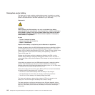
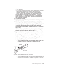
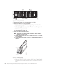
b. Unlock the SFP module latch:
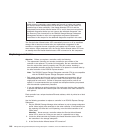
v For SFP modules that contain plastic tabs, unlock the SFP module latch
by pulling the plastic tab outward 10°, as shown in Figure 105.
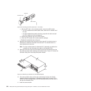
v For SFP modules that contain wire tabs, unlock the SFP module latch by
pulling the wire latch outward 90°, as shown in Figure 106 on page 148.
Protective cap
SFP module
10
o
Plastic tab
F10ug009
Figure 105. Unlocking the SFP module latch - plastic variety
Chapter 5. Replacing components 147