


subsystems such as DS4100 or DS4300 storage subsystems. The DS4700 Express
E-DDM option CRUs are not interchangeable with those of the DS4200 Express
and EXP420. When replacing an E-DDM CRU, be sure to order and install the
correct E-DDM CRU. Using non-supported E-DDM options or FRUs will result in the
E-DDM being locked out by the DS4700 Express controller firmware and might also
damage the drive connector in the enclosure midplane.
Attention:
1. After you remove a E-DDM CRU, wait 70 seconds before replacing or reseating
the E-DDM CRU to allow it to properly spin down. Failure to do so may cause
undesired events.
2. Never hot-swap a E-DDM CRU when its associated green Activity LED is
flashing. Hot-swap a E-DDM CRU only when its associated amber Fault LED
lights is not flashing or when the E-DDM is inactive and its associated green
Activity LED lights is not flashing.
Note: If the E-DDM you want to remove is not in a failed or bypass state, always
use the Storage Manager client program either to place it in a failed state or
to place the array that is associated with the E-DDM (or E-DDMs) in an
offline state before you remove it from the enclosure.
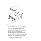
Controllers
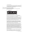
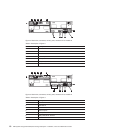
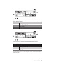
The DS4700 Express has two hot-swappable and redundant RAID controllers. The
controllers are located at the back of the storage subsystem. The left controller is
labeled controller A, and the right controller is labeled controller B. One controller
will continue to operate if the other controller fails.
The controllers contain the storage subsystem control logic, interface ports, and
LEDs. The controller on model 70 has two fibre channel host ports and the
controller on model 72 has four fibre channel host ports that you could use to
connect the storage subsystem to the host server. In addition, each controller for
both DS4700 Express subsystem models 70 and 72 has two fibre channel drive
ports for connecting to the DS4000 storage expansion enclosures and two Ethernet
ports for DS4700 Express subsystem management purposes. See Figure 2 on page
10.
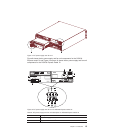
Although both controllers (A and B) are identical, they are seated in the DS4700
Express chassis in opposite orientations. See Figure 2 on page 10. If the controller
cannot fully be inserted in the controller bay, flip it 180 degrees and reinsert it. Do
not force fit because it may cause damage to the controller unit.
Connectors, switch, and enclosure ID
The controllers support fiber optic interfaces for both the host channel and drive
channel ports. The controllers also contain two Ethernet ports for storage
subsystem management purposes and a serial port that IBM Support uses to
perform problem recovery and troubleshooting procedures.
The default IP addresses for the Ethernet ports on controller A are 192.168.128.101
and 192.168.129.101. The default IP addresses for the Ethernet ports on controller
B are 192.168.128.102 and 192.168.129.102. The subnet mask for all cases are
255.255.255.0. See “Setting up IP addresses for DS4000 storage controllers” on
page 11 for more information.
The enclosure ID, comprised of two seven-segment numbers, is located on the
back of each controller next to the controller indicator lights. The two digits that
8 IBM System Storage DS4700 Express Storage Subsystem: Installation, User’s and Maintenance Guide