


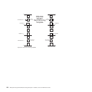


Appendix B. Rack mounting template
This appendix provides duplicate copies of the rack mounting templates. If you want
to tear out the templates from this document for easier use, use these copies rather
than those provided in “Installing the support rails” on page 36.
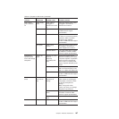
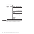
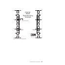
Use the following templates (Figure 121 on page 196 and Figure 122 on page 197)
to identify the proper locations for inserting M5 screws when mounting the support
rails and DS4700 Express to a rack. The locations for the M5 screws are
highlighted in the templates.
The DS4700 Express is 3 U high. Align the template with the rack at a U boundary.
U boundaries are shown as horizontal dashed lines in the rack mounting templates.
Note: The mounting holes that are shown in the following templates are square.
The holes in your rack might be round or square.
© Copyright IBM Corp. 2010 195