


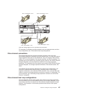
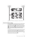
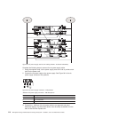
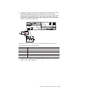

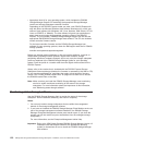

4. Complete the wiring from the disconnect device to the terminal marked -48V of
the Reliably grounded safety extra low voltage (SELV) dc power source.
Connect the POS RTN and ground lines of the dc power cable to the terminals
marked POS RTN and GND on the dc power source, as shown in Figure 95.
For maximum protection against power loss, connect each of the two dc power
supplies to a different power source.
Table 39. DC power source wiring descriptions
Number Description
1 Pin 1: -48 V dc
2 Pin 2: POS RTN
3 Pin 3: GND
4 DC power source
5 Disconnect device
5. Continue with “Powering on the storage subsystem” on page 119 for the initial
startup of the storage subsystem.
ds470097
2 3
1
4
5
Figure 95. DC wiring from DS4700 Express to disconnect device and dc power source
Chapter 3. Cabling the storage subsystem 115