


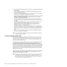

Table 6. DC power supply and fan unit description for DS4700 Express model 70 (continued)
Number Description
3 DC power connector A2
1
4 DC power switch
5 DC power supply and fan unit B
6 DC power connector B1
2
7 DC power connector B2
2
8 Pin 1: -48 V dc
9 Pin 2: POS RTN
10 Pin 3: GND
Notes:
1. The A1 and A2 dc connectors are keyed so that the dc cables are connected to the A1
and A2 connectors in only one way and in opposite orientation from each other. If the dc
cable does not fit the dc connector, flip it 180 degrees and try again. Do not force fit
because you might damage the connectors and short out the power supply.
2. The B1 and B2 dc connectors are keyed so that the dc cables are connected to the B1
and B2 connectors in only one way and in opposite orientation from each other. If the dc
cable does not fit the dc connector, flip it 180 degrees and try again. Do not force fit
because you might damage the connectors and short out the power supply.
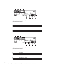
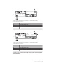
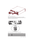
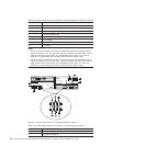
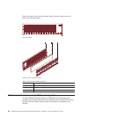
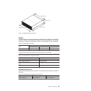
Table 7. DC power supply and fan unit description for DS4700 Express model 72
Number Description
1 DC power supply and fan unit A
2 DC power connector A1
1
ds470075
1
2
3
4
5
6
7
4
9
10
8
109
8
Figure 9. DC power supply and fan unit for DS4700 Express model 72
16 IBM System Storage DS4700 Express Storage Subsystem: Installation, User’s and Maintenance Guide