


Note: Make sure that the EMC gasket does not snag on the bezel.
d. Push the tray handle down until it latches into place.
Replacing hot-swap E-DDMs
E-DDM problems include any malfunctions that delay, interrupt, or prevent
successful I/O activity between the hosts and the E-DDMs in the storage
subsystem. This includes transmission problems between the host controllers and
the E-DDMs. This section explains how to replace a failed E-DDM.
Note: If you want to remove an E-DDM that is not in a failed or bypass state,
always use the Storage Manager client program either to place the E-DDM
in a failed state or to place the array that is associated with the E-DDM (or
E-DDMs) in an offline state before you remove it from the storage
subsystem.
Attention: Failure to replace the E-DDMs in their correct bays might result in loss
of data. If you are replacing an E-DDM that is part of a configured array and logical
drive, ensure that you install the replacement E-DDM in the correct bay. Check the
hardware and software documentation that is provided with your DS4000 to see if
there are restrictions regarding E-DDM configurations.
Complete the following steps to replace a hot-swap E-DDM:
1. Use the DS4000 Storage Management client software to print a new storage
system profile.
2. Determine the location of the E-DDM that you want to remove.
Attention: Never hot-swap a E-DDM CRU when its associated green Activity
LED is flashing. Hot-swap a E-DDM CRU only when its associated amber Fault
LED is lit and not flashing.
3. Put on antistatic protection.
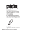
4. Remove the E-DDM CRU by doing the following:
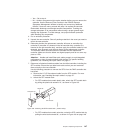
a. Release the latch on the E-DDM CRU by pressing on the inside of the
bottom of the tray handle, as shown by the arrow in Figure 111 on page 154.
b. Pull the tray handle out into the open position.
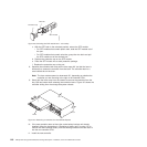
c. Pull the E-DDM CRU about 1/2 inch out of the bay and wait 70 seconds to
allow the E-DDM to properly spin down and the storage subsystem
controller to properly recognize that an E-DDM is removed from the
configuration. .
d. Verify that there is proper identification (such as a label) on the E-DDM
CRU, and then slide it completely out of the storage subsystem.
5. Unpack the new E-DDM. Save all packing material in case you need to return it.
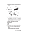
6. Install the new E-DDM CRU by doing the following:
a. Gently push the E-DDM CRU into the empty bay until the hinge of the tray
handle latches beneath the storage subsystem enclosure bezel.
b. Push the tray handle down into the closed (latched) position.
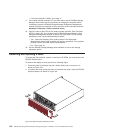
7. Check the E-DDM LEDs by doing the following:
v When a E-DDM is ready for use, the green Activity LED lights and the amber
Fault LED is off.
v If the amber Fault LED lights and is not flashing, remove the E-DDM from the
unit and wait 70 seconds; then, install the E-DDM again.
Chapter 5. Replacing components 155