


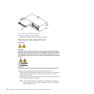
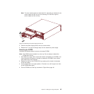
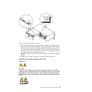
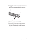
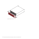

2. As you slide the controller into the empty slot, make sure the guide pins on the
side of the controller fit into the notches. After the guide pins fit into the notches
and the controller fits snugly into the bay, push the lever downward or upward
90°, depending on whether the controller is inserted in the A or B controller bay
to fully latch it into place. Do not force fit. The controller is designed to prevent it
from being inserted into the chassis incorrectly.
Attention: Make sure that the levers lock into place in the storage subsystem
chassis.
3. Repeat step 1 on page 48 and step 2 to replace the second controller.
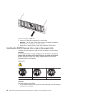
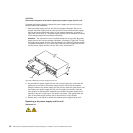
Replacing an ac power supply and fan unit
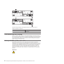
Statement 5:
CAUTION:
The power control button on the device and the power switch on the power
supply do not turn off the electrical current supplied to the device. The device
also might have more than one power cord. To remove all electrical current
from the device, ensure that all power cords are disconnected from the power
source.
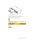
1
2
Lever
Guide pin
Notch
Figure 27. Removing and replacing a controller
Chapter 2. Installing the storage subsystem 49