


PowerLogic™ PM5300 series user guide Chapter 3—Hardware Reference
© 2014 Schneider Electric All Rights Reserved 25
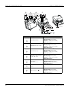
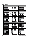
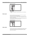
Voltage and current input wiring
For wiring instructions and safety precautions, see the meter installation sheet that was
shipped with your meter, or download a copy at www.schneider-electric.com.
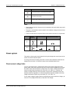
Voltage input protection
The meter’s voltage inputs must be wired to fuses/breakers and a disconnect switch. If
using a voltage transformer (VT), both primary and secondary sides of the VT must be
wired to fuses/breakers and disconnect switches.
• Clearly label the device’s disconnect circuit mechanism and install it within easy reach
of the operator.
• The fuses / circuit breakers must be rated for the installation voltage and sized for the
available fault current.
• Fuse for neutral terminal is required if the source neutral connection is not grounded.
See the meter installation sheet for fuse ratings.
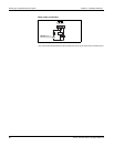
Current input protection
For all connected current inputs, use a CT shorting block to short-circuit the secondary
leads of the CTs before removing the current input connections to the meter.
NOTE: Ground any unused current inputs.
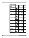
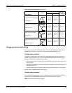
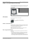
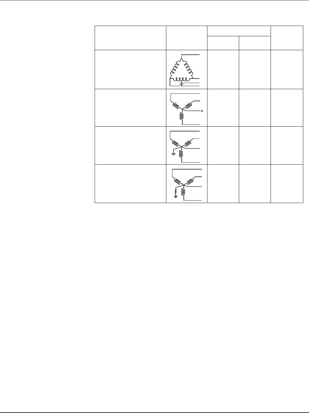
3-phase 4-wire Delta center-tapped
—
3PH4W Dlt Ctr Tp
240 V L-N /
415 V L-N /
480 V L-L
240 V L-N /
415 V L-N /
480 V L-L
3 VT
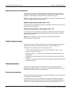
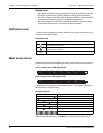
3-phase 4-wire ungrounded Wye
—
3PH4W Wye Ungnd
347 V L-N /
600 V L-L
347 V L-N /
600 V L-L
3 VT or 2 VT
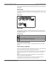
3-phase 4-wire grounded Wye
—
3PH4W Wye Gnd
347 V L-N /
600 V L-L
400 V L-N /
690 V L-L
3 VT or 2 VT
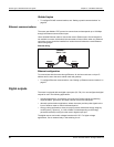
3-phase 4-wire resistance-grounded
Wye
—
3PH4W Wye Res Gnd
347 V L-N /
600 V L-L
347 V L-N /
600 V L-L
3 VT or 2 VT
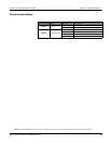
Power system setup parameters (continued)
Power system description
—
Meter setting
Symbol
Direct connect maximum
# of VTs
(if required)
UL IEC
N
N
N