


PowerLogic™ PM5300 series user guide Chapter 3—Hardware Reference
© 2014 Schneider Electric All Rights Reserved 27
communicate with the slave devices, an RS-232 to RS-485 converter can be used as the
master device.
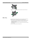
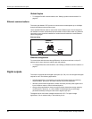
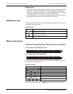
RS-485 wiring
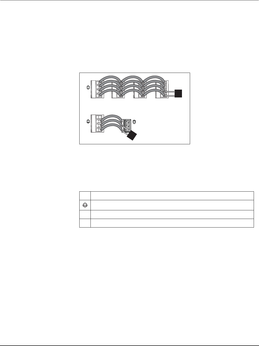
Connect the devices on the RS-485 bus in a point-to-point configuration, with the (+) and
(-) terminals from one device connected to the corresponding (+) and (-) terminals on the
next device.
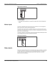
RS-485 cable
Use a shielded 1.5 twisted pair or 2 twisted pair RS-485 cable to wire the devices. Use
one twisted pair to connect the (+) and (-) terminals, and use the other insulated wire to
connect the C terminals.
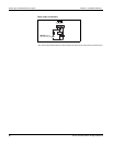
RS-485 maximum cable length
The total distance for devices connected on an RS-485 bus should not exceed 1200 m
(4000 ft).
RS-485 network configuration
After you have wired the RS-485 port and powered up the meter, you must configure the
serial communications port in order to communicate with the meter.
Each device on the same RS-485 communications bus must have a unique address and
all connected devices must be set to the same protocol, baud rate, and parity (data
format).
NOTE: To communicate with the meter using ION Setup, you must set the parity to
“None” for all devices in the RS-485 network.
For meters that do not have a display, you must first wire and configure each one
separately before connecting these meters to the same RS-485 bus.
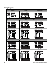
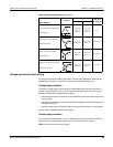
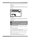
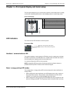
RS-485 wiring
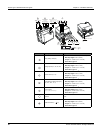
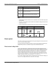
RS-485 terminals
C
Common. This provides the voltage reference (zero volts) for the data plus and data minus signals.
Shield. Connect the bare wire to this terminal to help suppress signal noise that may be present.
Ground the shield wiring at one end only (either at the master or the last slave device, but not both).
-
Data minus. This transmits/receives the inverting data signals.
+
Data plus. This transmits/receives the non-inverting data signal.
+
-
C
D1 (+)
D0 (-)
+
-
C
120 Ω
120 Ω
Master Slaves