


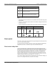
PowerLogic™ PM5300 series user guide Chapter 4—Front panel display and meter setup
© 2014 Schneider Electric All Rights Reserved 31
Chapter 4—Front panel display and meter setup
The front panel display lets you use the meter to perform various tasks such as setting
up the meter, displaying data screens, acknowledging alarms, or performing resets.
LED indicators
The meter has two LED indicators on the front panel.
Heartbeat / communications LED
The (green) heartbeat / communications LED blinks at a slow, steady rate to indicate
the meter is operational. The LED flashes at a variable, faster rate when the meter is
communicating over a Modbus serial communications port.
You cannot configure this LED for other purposes.
NOTE: A heartbeat LED that remains lit and does not blink (or flash) indicates a
possible hardware problem. Please contact Technical Support.
Alarm / energy pulsing LED modes
The (orange) alarm / energy pulsing LED can be configured for alarm notification or
energy pulsing.
• When configured for alarm notification, this LED flashes when a high, medium or
low priority alarm is active. This provides a visual indication of an active alarm
condition, or an inactive but unacknowledged high priority alarm.
• When configured for energy pulsing, this LED flashes at a rate proportional to the
amount of energy consumed. This is typically used to verify the meter’s accuracy.
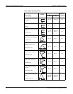
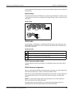
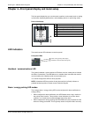
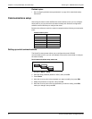
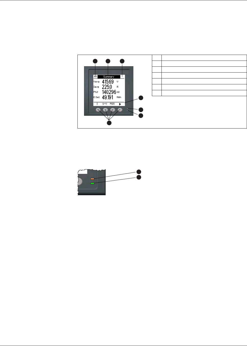
Parts of the display
A Navigation / menu selection buttons
B Heartbeat / communications LED (green)
C Alarm / energy pulsing LED (orange)
D Navigation symbols or menu options
E Right notification area
F Screen title
G Left notification area
B
A
C
G
E
F
D
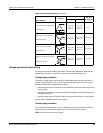
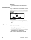
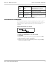
Front panel LEDs
Alarm / energy pulsing LED (orange)
Heartbeat / communications LED (green)
C
B