PowerLogic™ PM5300 series user guide Chapter 6—Input / Output
© 2014 Schneider Electric All Rights Reserved 49
Chapter 6—Input / Output
This section describes the meter’s I/O (input/output) features.
Based on the reference model, the meter is equipped with the following status input,
digital output and relay output ports:
Status Input, Digital Output Ports and Relay Output Ports
NOTE: Relay = Form A relay
After you wire the meter’s I/O ports, you can configure these ports so you can use the
meter to perform I/O functions.
Status input applications
Status inputs are typically used for monitoring the status of external contacts or circuit
breakers.
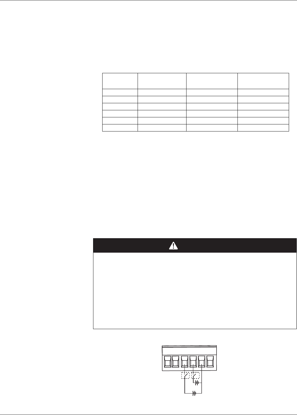
The meter’s status inputs require either an external voltage source or whetting voltage
(provided in the meter) to detect the status input’s ON/OFF state. The meter detects an
ON state if the external voltage appearing at the status input is within its operating
range.
Reference
Models
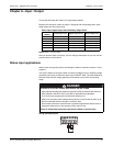
Status Input Ports Digital Output Ports Relay Output Ports
PM5310 2 (S1+, S2+) 2 (D1+, D2+) -
PM5320 2 (S1+, S2+) 2 (D1+, D2+) -
PM5330 2 (S1+, S2+) 2 (D1+, D2+) 2 (Relay 1, Relay 2)
PM5331 2 (S1+, S2+) 2 (D1+, D2+) 2 (Relay 1, Relay 2)
PM5340 2 (S1+, S2+) 2 (D1+, D2+) 2 (Relay 1, Relay 2)
PM5341 2 (S1+, S2+) 2 (D1+, D2+) 2 (Relay 1, Relay 2)
DANGER
HAZARD OF ELECTRIC SHOCK, EXPLOSION, OR ARC FLASH
• Apply appropriate personal protective equipment (PPE) and follow safe electrical
work practices. See NFPA 70E in the USA or applicable local standards.
• Turn off all power supplying this device before working on it.
• Always use a properly rated voltage sensing device to confirm that all power is off.
• Do not exceed the device’s ratings for maximum limits.
• Do not use this device for critical control or protection applications where human or
equipment safety relies on the operation of the control circuit.
Failure to follow these instructions will result in death or serious injury.
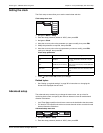
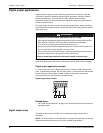
Wiring the status inputs
S1 S2D1 D2 -/C +
18-36 Vdc
(60) (62)
(40) (42) (57) (56)
18-36 Vdc


