


PowerLogic™ PM5300 series user guide Chapter 5—Viewing Meter Data
© 2014 Schneider Electric All Rights Reserved 47
Related topics
• See “Power quality” on page 89.
Related topics
• See “Alarms” on page 63.
Related topics
• See “Input / Output” on page 49.
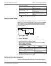
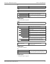
PF
True Per phase and total true power factor values and sign.
Disp Per phase and total displacement power factor values and sign.
Hz [F]
Frequency (Freq), average voltage and current (Vavg, Iavg) and power factor (PF) values.
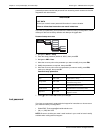
THD
THD
THD (ratio of harmonic content to the fundamental) for current,
line-to-line voltage, and line-to-neutral voltage.
Amps [I], V L-L [U], V L-N [V]
thd thd (ratio of harmonic content to the rms value of total harmonic
content) for current, line-to-line voltage, and line-to-neutral
voltage.
Amps [I], V L-L [U], V L-N [V]
Unbal
Percent unbalance readings for line-to-line voltage (V L-L [U]), line-to-neutral voltage (V L-N [V]) and current
(Amps [I]).
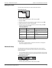
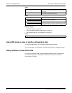
MnMx
MnMx
Summary of maximum values for line-to-line voltage, line-to-
neutral voltage, phase current and total power.
Amps [I] Minimum and maximum values for phase current.
Volts
Minimum and maximum values for line-to-line voltage and line-
to-neutral voltage.
VL-L, VL-N
Power
Minimum and maximum values for active, reactive, and apparent
power.
Active, Reac, Apr
PF
Minimum and maximum values for true and displacement PF and
PF sign.
True, Disp
Hz Minimum and maximum values for frequency.
THD
Minimum and maximum values for total harmonic distortion (THD
or thd).
THD, thd
Amps, VL-L, VL-N
THD or thd minimum and maximum values for phase or neutral
current, line-to-line voltage and line-to-neutral voltage.
Unbal
Minimum and maximum values for current unbalance, line-to-line
voltage unbalance and line-to-neutral voltage unbalance..
Amps, VL-L, VL-N
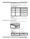
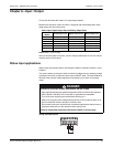
Alarm
Active, Hist, Count, Unack
Lists all active alarms, past alarms (Hist), the total number each
standard alarm has been tripped (Count), and all
unacknowledged alarms.
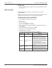
I/O
D Out Current status (on or off) of the selected digital output, status
input or relay. Counter shows the total number of times an off-to-
on change of state is detected. Timer shows the total time (in
seconds) that a digital output, status input or relay is in the on
state.
S In
Relay