


58 © 2014 Schneider Electric All Rights Reserved
Chapter 6—Input / Output PowerLogic™ PM5300 series user guide
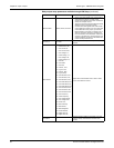
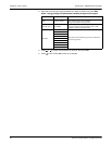
Behavior Mode Normal, Timed, Coil Hold
• Normal: this mode applies when control mode is
set to External or Alarm. The relay output
remains in the ON state until an OFF command is
sent by the computer or PLC.
• Timed: the relay output remains ON for the period
defined by the On Time setup register.
• Coil Hold: this mode applies when control mode
is set to External or Alarm. For a unary alarm that
is associated with a relay output, you must set
Behavior Mode to Coil Hold. The output turns on
when the “energize” command is received and
turns off when the “coil hold release” command is
received. In the event of a control power loss, the
output remembers and returns to the state it was
in when control power was lost.
On Time (s) 0 to 9999
This setting defines the pulse width (ON time) in
seconds.
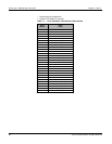
Select Alarms
1. Over Current, Ph;
2. Under Current, Ph;
3. Over Current, N;
4. Over Current, Gnd;
5. Over Voltage, L-L;
6. Under Voltage, L-L;
7. Over Voltage, L-N;
8. Under Voltage L-N;
9. Over kW;
10. Over kVAR;
11. Over kVA;
12. Lead PF, True;
13. Lag PF, True;
14. Lead PF, Disp;
15. Lag PF, Disp;
16. Over kW Dmd, Pres;
17. Over kW Dmd, Last;
18. Over kW Dmd, Pred;
19. Over kVAR Dmd,Pres;
20. Over kVAR Dmd,Last;
21. Over kVAR Dmd,Pred;
22. Over kVA Dmd, Pres;
23. Over kVA Dmd, Last;
24. Over kVA Dmd, Pred;
25. Over Frequency;
26. Under Frequency;
27. Over Voltage Unbal;
28. Over Voltage THD;
29. Phase Loss;
30. Meter Powerup;
31. Meter Reset;
32. Meter Diagnostic;
33. Phase Reversal;
34. Digital Alarm S1;
35. Digital Alarm S2;
Applies when Control Mode is set to Alarm. Select
one or more alarms to monitor.
Associations —
This field displays additional information if the relay
output is already associated with another meter
function.
Relay output setup parameters available through ION Setup (continued)
Parameter Values Description