


106
Chapter 4 Working Inside Your System
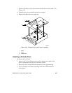
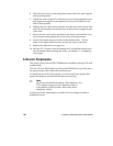
4. Place the drive carrier on the component-side of the drive, and align the
three mounting holes.
5. Attach the carrier to the drive with three screws of the appropriate size
and length (not supplied), and tighten the screws firmly (between 4.0
and 6.0 inch-pounds).
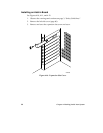
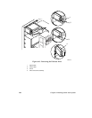
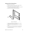
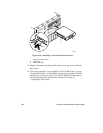
6. Position the drive and carrier assembly over the slots in the chassis wall,
and slide the assembly toward the front of the system to engage its tabs
in the slots.
7. Secure the drive and carrier assembly to the chassis wall with the screw
you removed earlier; tighten the screw firmly (6.0 inch-pounds).
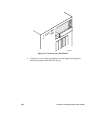
8. Connect the signal and power cables to the diskette drive. The red
stripe on the signal cable must face toward the center of the drive.
9. Replace the right side cover (page 81).
10. Run the SCU to specify that the diskette drive is installed in the system.
For information about running this utility, see Chapter 3, “Configuring
The System.”
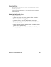
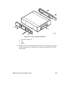
5.25-inch Peripherals
The system comes with an IDE CD-ROM drive installed in the top 5.25-inch
peripheral bay.
The two 5.25-inch half-height bays below the CD-ROM drive provide space
for tape backup or other removable media devices.
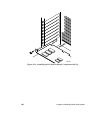
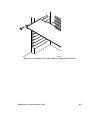
To install devices in the 5.25-inch bays, you must remove the plastic filler
panels and stainless steel EMI shields that cover the bays.
✏
Note
We do not recommend mounting a hard disk drive in a
5.25-inch bay because the drive generates EMI, its
susceptibility to ESD increases, and it may not be
adequately cooled.
Contact your sales representative or dealer for a list of approved add-in
peripheral devices.